184
F(L)CS Data Acquisition
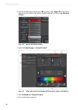
Figure 160:
Optimization of the correction ring in the Setup Corr-ring step
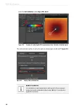
5. Move the focus using the z-drive of the microscope stand until you see the two reflection
lines that appear between the immersion and the glass and between the glass and the
specimen (
, only visible simultaneously at zoom 1).
Figure 161:
Reflection at the transition between the cover slip and the immersion water (top) and
between the cover slip and the specimen (bottom) on the inverted stand. The objective is
optimized relative to the bottom reflection. (The top and bottom reflection are
simultaneously visible only for zoom 1. However, this can be set only if the objective cap
was previously disabled in LAS AF.)
Summary of Contents for TCS SP8 SMD
Page 1: ...10 Living up to Life User Manual Leica TCS SP8 SMD for FCS FLIM and FLCS ...
Page 4: ...4 Copyright ...
Page 14: ...14 Contents ...
Page 18: ...18 Intended Use ...
Page 20: ...20 Liability and Warranty ...
Page 28: ...28 General Safety Notes ...
Page 32: ...32 Additional Notes on Handling the System ...
Page 44: ...44 System Overview and Properties ...
Page 60: ...60 SMD Components Figure 31 DSN 102 Dual SPAD Power Supply ...
Page 80: ...80 Safety Features ...
Page 102: ...102 Switching On the System ...
Page 116: ...116 LAS AF ...
Page 214: ...214 Changing the Specimen ...
Page 216: ...216 Changing the Objective ...
Page 238: ...238 Switching Off the System ...
Page 242: ...242 Repairs and Service Work ...
Page 244: ...244 Maintenance ...
Page 246: ...246 Disassembly and Transport ...
Page 248: ...248 Disposal ...
Page 254: ...254 Contact ...
Page 256: ...256 Recommended Literature ...
Page 266: ...266 Appendix Figure 225 Declaration of conformity ...
Page 268: ...268 Appendix ...
Page 269: ......


