


131
FLIM Data Acquisition
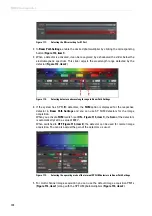
Figure 116:
Dialog for AOBS configuration
2. Choose a suitable laser line and adjust the intensity to the desired level using the AOTF
slider.
3. If the system has a multifunction port (
MFP
), set it to
Substrate
.
16.1.2.2
Using MP Lasers
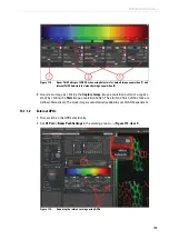
1. For MP scanning operations, select the desired wavelength in
Beam Path Settings
.
2. Choose a suitable neutral density filter for the attenuation using the
Trans
slider and/or
adjust the electro-optical modulator (EOM) using the
Gain
and
Offset
sliders.
3. If the system has a multifunction port, it should be set to
SP680
or
SP700
.
For more detailed information about switching on the MP lasers, refer to
.
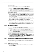
16.1.2.3
Using Pulsed VIS Lasers
1. Close the shutter of the continuous wave VIS laser in
Beam Path Settings
and move all
sliders to the 0 position.
2. Open the shutter for pulsed lasers by activating the corresponding button (
).
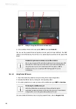
3. Activate the desired laser by moving the corresponding slider upwards (
).
Prevent light incidence during MP FLIM measurement
During an MP FLIM measurement (particularly with HyD RLD), the light in
the room should be switched off and the shutter of the fluorescence lamp
should be closed. Furthermore, the iris diaphragm on the condenser
should be completely closed.
Controlling laser intensity of the pulsed laser
For pulsed lasers, the slider does not affect the laser intensity. Laser
intensity needs to be controlled at the desired laser.
Summary of Contents for TCS SP8 SMD
Page 1: ...10 Living up to Life User Manual Leica TCS SP8 SMD for FCS FLIM and FLCS ...
Page 4: ...4 Copyright ...
Page 14: ...14 Contents ...
Page 18: ...18 Intended Use ...
Page 20: ...20 Liability and Warranty ...
Page 28: ...28 General Safety Notes ...
Page 32: ...32 Additional Notes on Handling the System ...
Page 44: ...44 System Overview and Properties ...
Page 60: ...60 SMD Components Figure 31 DSN 102 Dual SPAD Power Supply ...
Page 80: ...80 Safety Features ...
Page 102: ...102 Switching On the System ...
Page 116: ...116 LAS AF ...
Page 214: ...214 Changing the Specimen ...
Page 216: ...216 Changing the Objective ...
Page 238: ...238 Switching Off the System ...
Page 242: ...242 Repairs and Service Work ...
Page 244: ...244 Maintenance ...
Page 246: ...246 Disassembly and Transport ...
Page 248: ...248 Disposal ...
Page 254: ...254 Contact ...
Page 256: ...256 Recommended Literature ...
Page 266: ...266 Appendix Figure 225 Declaration of conformity ...
Page 268: ...268 Appendix ...
Page 269: ......


