134
FLIM Data Acquisition
16.2
Setup FLIM Step – Optimizing the FLIM Measurement
Conditions
Go to the
Setup FLIM
step in the FLIM Wizard. Now set the instrument parameters for a FLIM
measurement.
16.2.1
Selecting FLIM Detectors
For FLIM measurements, special detectors have to be used that are able to do single photon
counting with a high time resolution. With FLIM excitation in the UV and VIS range, FLIM
detectors are used in a descanned position: The light is either split off at the X1 port to APDs
or a FLIM photomultiplier (external detection) or sent to the SP detection module on the SP
FLIM photomultiplier (internal detection). With MP excitation, FLIM detectors may optionally
be used at a non-descanned position. When doing so, the fluorescent light on the stand is
split off directly behind the objective. The following options are available:
• External FLIM detection using two APDs
• External FLIM detection using a FLIM PMT
• Internal FLIM detection using one or two SP FLIM PMTs
• External FLIM detection using two
APDs and internal FLIM detection using two SP FLIM
PMTs; the internal and external detectors can only be used in alternation for this
• Detection at NDD position with one or two
HyD RLD
If you use a system with both internal and external FLIM detection, first you have to select
the detectors you want to use:
1. Select the
Setup
tab (
).
2. In the
FLIM Detector
pull-down menu, select either
Internal (SP FLIM)
for internal SP
FLIM detection,
External
for external detection at the X1 port, or
Non-descanned (MP
FLIM)
for detection at an NDD position (
).
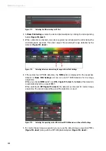
Figure 119:
Setup FLIM step
Summary of Contents for TCS SP8 SMD
Page 1: ...10 Living up to Life User Manual Leica TCS SP8 SMD for FCS FLIM and FLCS ...
Page 4: ...4 Copyright ...
Page 14: ...14 Contents ...
Page 18: ...18 Intended Use ...
Page 20: ...20 Liability and Warranty ...
Page 28: ...28 General Safety Notes ...
Page 32: ...32 Additional Notes on Handling the System ...
Page 44: ...44 System Overview and Properties ...
Page 60: ...60 SMD Components Figure 31 DSN 102 Dual SPAD Power Supply ...
Page 80: ...80 Safety Features ...
Page 102: ...102 Switching On the System ...
Page 116: ...116 LAS AF ...
Page 214: ...214 Changing the Specimen ...
Page 216: ...216 Changing the Objective ...
Page 238: ...238 Switching Off the System ...
Page 242: ...242 Repairs and Service Work ...
Page 244: ...244 Maintenance ...
Page 246: ...246 Disassembly and Transport ...
Page 248: ...248 Disposal ...
Page 254: ...254 Contact ...
Page 256: ...256 Recommended Literature ...
Page 266: ...266 Appendix Figure 225 Declaration of conformity ...
Page 268: ...268 Appendix ...
Page 269: ......


