123
Selecting the Laser
Table 18: MFP settings based on the excitation wavelength used
You can use pulsed VIS lasers together with a pulsed UV laser. The MFP setting is not
influenced by UV. It is defined by the selection of the pulsed VIS lasers.
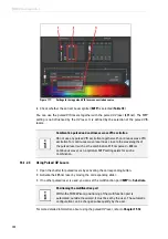
9. If you work on a beam splitter system, set the
beam splitter
to
Substrate
in the
Beam Path
Settings
in LAS AF (
). In case you want to use a pulsed laser combined with a
continuous wave laser line, chose the corresponding main beam splitter that reflects the
continuous wave laser line into the scan head.
Figure 105:
Setting the beam splitter to substrate
Configuration
Lasers used
MFP settings in LAS AF
405
405
Substrate
405+440
405
440
Substrate
RSP 445
405+470
405
405+470
470
Substrate
SD 470
SD 470
405+470+640
405
405+470
405+640
470
470+640
640
Substrate
DD 470+640
DD 470+640
DD 470+640
DD 470+640
DD 470+640
440
440
RSP 445
440+470
440
470
RSP 445
SD 470
470
470
RSP 445
470+640
470
470+640
640
DD 470+640
DD 470+640
DD 470+640
Combination pulsed and continuous wave VIS excitation
Do not use any pulsed VIS excitation together with continuous wave VIS
excitation for continuous wave laser lines close to the wavelengths of
the pulsed laser (such as the combination 470 nm 488 nm
continuous wave), as no optimum MFP setting exists for such a
combination.
Summary of Contents for TCS SP8 SMD
Page 1: ...10 Living up to Life User Manual Leica TCS SP8 SMD for FCS FLIM and FLCS ...
Page 4: ...4 Copyright ...
Page 14: ...14 Contents ...
Page 18: ...18 Intended Use ...
Page 20: ...20 Liability and Warranty ...
Page 28: ...28 General Safety Notes ...
Page 32: ...32 Additional Notes on Handling the System ...
Page 44: ...44 System Overview and Properties ...
Page 60: ...60 SMD Components Figure 31 DSN 102 Dual SPAD Power Supply ...
Page 80: ...80 Safety Features ...
Page 102: ...102 Switching On the System ...
Page 116: ...116 LAS AF ...
Page 214: ...214 Changing the Specimen ...
Page 216: ...216 Changing the Objective ...
Page 238: ...238 Switching Off the System ...
Page 242: ...242 Repairs and Service Work ...
Page 244: ...244 Maintenance ...
Page 246: ...246 Disassembly and Transport ...
Page 248: ...248 Disposal ...
Page 254: ...254 Contact ...
Page 256: ...256 Recommended Literature ...
Page 266: ...266 Appendix Figure 225 Declaration of conformity ...
Page 268: ...268 Appendix ...
Page 269: ......


