190
F(L)CS Data Acquisition
18.2
Setup Imaging Step – Image Acquisition
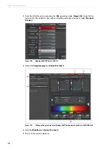
1. Start the FCS Wizard in LAS AF. To do so, open the operating mode selector and select
FCS
.
2. For applications in cells or tissues, in the
Setup Imaging
step you first create an xy scan
of your specimen in the desired z plane, or you acquire an xyz stack (with z-Galvo).
3. If you would like to display a 'z-section' of your specimen, you can also acquire an xz
image or an xzy stack. This might be especially of interest when working on membranes.
Other imaging modes (like time series or lambda stack) are not supported. The image
acquisition procedure is the same as the general procedure without using the FCS Wizard.
18.2.1
Selecting Detectors for the Image Acquisition
You can use photomultipliers as well as APDs for the image acquisition. Photomultipliers are
distinguished by having wide dynamic range; APDs are distinguished by higher detection
quantum efficiency. PE APDs are distinguished by very good red sensitivity.
18.2.1.1
Photomultiplier (PMT) / Internal Hybrid Detector (HyD)
1. Check that the external port X1 is switched to the
Mirror
position (
).
2. In the beam path schema, activate the desired PMTs/HyD by clicking the appropriate
check box.
3. Select the desired spectral range for detection.
4. Select low laser intensities.
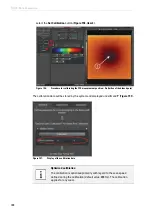
5. You may also have to adapt the color look-up table (LUT). Click the color scale to call up
the LUT selection dialog. There, you can select color look-up tables (LUT) for displaying
the images to be acquired and create user-defined color look-up tables.
6. Optimize the image quality. The functions for this are the same as outside the wizard.
7. Acquire an image by clicking the
Capture
image acquisition button or acquire an xyz or
xzy stack by clicking the
Start
image acquisition button. The start and finish of the stack
are defined interactively, in the usual way. The stack image is automatically added to
your LAS AF experiment.
18.2.1.2
PE / MPD APDs
1. First, switch on the APDs on the APD or DSN control unit electrically.
2. Set the external port X1 (
X1 Port
) to the position
---
).
3. Deactivate all photomultipliers in
Beam Path Settings
.
4. Activate the APDs by clicking the corresponding check boxes (
).
5. Select low laser intensities.
6. You may also have to adapt the color look-up table (LUT). Click the color scale to call up
the
LUT Selection
dialog. There, you can select color look-up tables (LUT) for displaying
the images to be acquired and create user-defined color look-up tables.
You can also configure the intensity setting via
Gain
and the control panel. This function
Summary of Contents for TCS SP8 SMD
Page 1: ...10 Living up to Life User Manual Leica TCS SP8 SMD for FCS FLIM and FLCS ...
Page 4: ...4 Copyright ...
Page 14: ...14 Contents ...
Page 18: ...18 Intended Use ...
Page 20: ...20 Liability and Warranty ...
Page 28: ...28 General Safety Notes ...
Page 32: ...32 Additional Notes on Handling the System ...
Page 44: ...44 System Overview and Properties ...
Page 60: ...60 SMD Components Figure 31 DSN 102 Dual SPAD Power Supply ...
Page 80: ...80 Safety Features ...
Page 102: ...102 Switching On the System ...
Page 116: ...116 LAS AF ...
Page 214: ...214 Changing the Specimen ...
Page 216: ...216 Changing the Objective ...
Page 238: ...238 Switching Off the System ...
Page 242: ...242 Repairs and Service Work ...
Page 244: ...244 Maintenance ...
Page 246: ...246 Disassembly and Transport ...
Page 248: ...248 Disposal ...
Page 254: ...254 Contact ...
Page 256: ...256 Recommended Literature ...
Page 266: ...266 Appendix Figure 225 Declaration of conformity ...
Page 268: ...268 Appendix ...
Page 269: ......


