ADwin-Pro
Hardware, manual version 2.9, June 2006
61
Pro I: Analog Input Modules
Pro-AIn-32/16 Rev. B
ADwin
5.5.11 Pro-AIn-32/16 Rev. B
To this module you find an improved successor module
(see
).
The analog input module Pro-AIn-32/16RB has a 16-bit ADC and a program-
mable gain amplifier (PGA). It has 32 single-ended or 16 differential inputs
(software selectable). The inputs are connected on a 37-pin DSUB socket. The
module can be combined with Pro-TC and Pro-PT modules.
The module Pro-AIn-32/16RB is equipped with an input voltage range of ± 10V
and a gain amplifier, programmable by software to 1, 2, 4 or 8. The adjustment
of gain and offset is made by software (see
chapter 6.3.1 "Calibration per Soft-
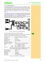
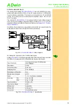
Fig. 103 –
: Block diagram
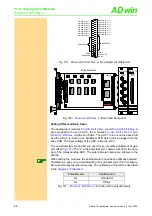
On Startup the module is set to 16 differential inputs.
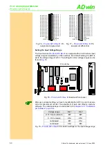
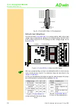
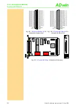
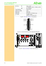
Figures
and
show the pin assignments of the module. Please consider
the different pin assignment for differential and single-ended inputs.
.
ADwi
n
-Pro
bus
A
D
1
330k
330k
2
330k
330k
32
330k
330k
. . . . . . . . .
Addr.
Data
Data
Register
Address
Decoder
Data
PGA
Vu= 1, 2, 4, 8
3
4
31
.
. . . . . . . .
MUX
Input channels:
32single-ended oder 16 differetial;
via multiplexer
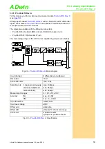
Resolution:
16 bit
Conversion time:
max. 8µs
Sampling rate:
max. 100ksps
Multiplexer settling time:
14µs
Measurement ranges:
±10V
Gain:
1, 2, 4, 8 software selectable
Accuracy
INL
max. ±3 LSB
DNL
max. +3, -2 LSB
Input resistance:
330k
Ω
, ±2%
Input over-voltage:
±17V
Offset error:
adjustable
Offset drift:
±20 ppm/ºC
Connector:
37-pin DSub socket
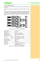
Fig. 104 –
: Specification


