Calculation basis
ADwin
192
ADwin-Pro
Hardware, manual version 2.9, June 2006
6.2 Calculation basis
Voltage range
The standard voltage range of the analog inputs/outputs of the
ADwin
systems
is -10V … +10V (bipolar 20 Volt).
The voltage ranges of the
ADwin-Pro
system can additionally be set to
-5V…+5V (bipolar 10 Volt) and 0V…+10V (unipolar 10 Volt) by jumper.
Allocating digits to
voltage
The 65536 (2
16
) digits are allocated to the corresponding voltage ranges of the
ADC and DAC in such a manner that the value for
– 0 (zero) digits corresponds to the maximum negative voltage.
– 65535 digits correspond to the maximum positive voltage.
The value for 65536 digits, exactly 10 Volt, is therefore just beyond the mea-
surement range, therefore you get for the 16 bit AD or DA conversion a maxi-
mum voltage value of 9.999695 Volt, and for the 12 bit AD conversion a value
of 9.995117 Volt.
Zero offset
In bipolar settings this results in a zero offset, called offset in the following text.
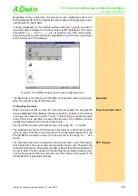
The offset has the following value:
V
OFF
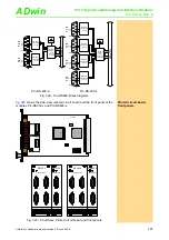
Least Significant bit
V
LSB
The value V
LSB
defines the voltage, which corresponds to the least significant
bit. The value in the standard setting is
– with 16 bit converters: 20V ./. 2
16
= 305.175µV
– with 12 bit converters: 20V ./. 2
12
= 4.8828mV
– Further values of V
LSB
can be found in
).
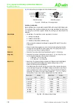
Gain k
V
When using Pro-AIn modules with programmable gain arrays (PGA), you can
amplify the input voltage by factors 2, 4 and 8. Thus, the measurement range
gets smaller by the corresponding gain factor k
V
.
Please pay attention to the fact that also the interference signals are amplified
when using applications with k
V
> 1. These can be reduced by programming
digital filters in
ADbasic
.
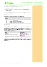
Allocating the bits
In order to get the same allocation of bits during measurements with the 12 bit
ADC as with a 16 bit ADC, the converted value is presented left-aligned in the
lower word (16 bit) with the 12 bit ADC. The least 4 significant bits are always
0 (see
).
Explanation to
The 4096 digits of the 12 bit ADC are mapped to the 65535 digits of the 16 bit
ADC. Therefore, 16 digits of the 16 bit ADC correspond to one digit of the 12
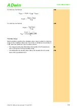
bit ADC.The following equations apply therefore for both ADC types.
Offset V
OFF
with setting
-10V
bipolar ±10 Volt (-10V…+10V)
-5V
bipolar ±5 Volt
(-5V…+5V)
0V
unipolar 10V
(0V…+10V)
bit-No.
31
…
16
15
14
13
12
11
10
09
08
07
06
05
04
03
02
01
00
32 bit-
Memory
0
(upper word)
12 bit value of the 12 bit-ADC in the lower word (left aligned)
0
0
0
0
16 bit value of the 16 bit-ADC in the lower word
Abb. 326 – Bit allocation of 12 bit-ADC and 16 bit-ADC

