Pro I: Signal Conditioning and Interface Modules
Pro-CAN-x Rev. A
ADwin
170
ADwin-Pro
Hardware, manual version 2.9, June 2006
5.9.6 Pro-CAN-x Rev. A
The module Pro-CAN has 1 or 2 CAN interfaces, a high speed or a low speed
version. The names for the module versions are shown in the table below:
CAN Controller
The CAN bus interface is equipped with the Intel
®
CAN controller AN82527
which works according to the specification CAN 2.0 parts A and B as well as
to ISO 11898. You program the interface with
ADbasic
instructions, which are
directly accessing the controller’s registers.
Message
Messages sent via CAN bus are data telegrams with up to 8 bytes, which are
characterized by so-called identifiers. The CAN controller of the DIO1 add-on
supports identifiers with a length of 11 bit and 29 bit. The communication, that
means the management of bus messages, is effected by 15 message objects.
The 255 registers are used for configuration and status display of the CAN con-
troller. Here the bus speed and interrupt handling, etc. are set (see separate
documentation "82527 - Serial Communications Controller, Architectural Over-
view" by Intel
®
)
The CAN bus can be set to frequencies of up to 1 MHz and is usually operated
with 1MHz; with low speed CAN the max. frequency is 125kHz. The CAN bus
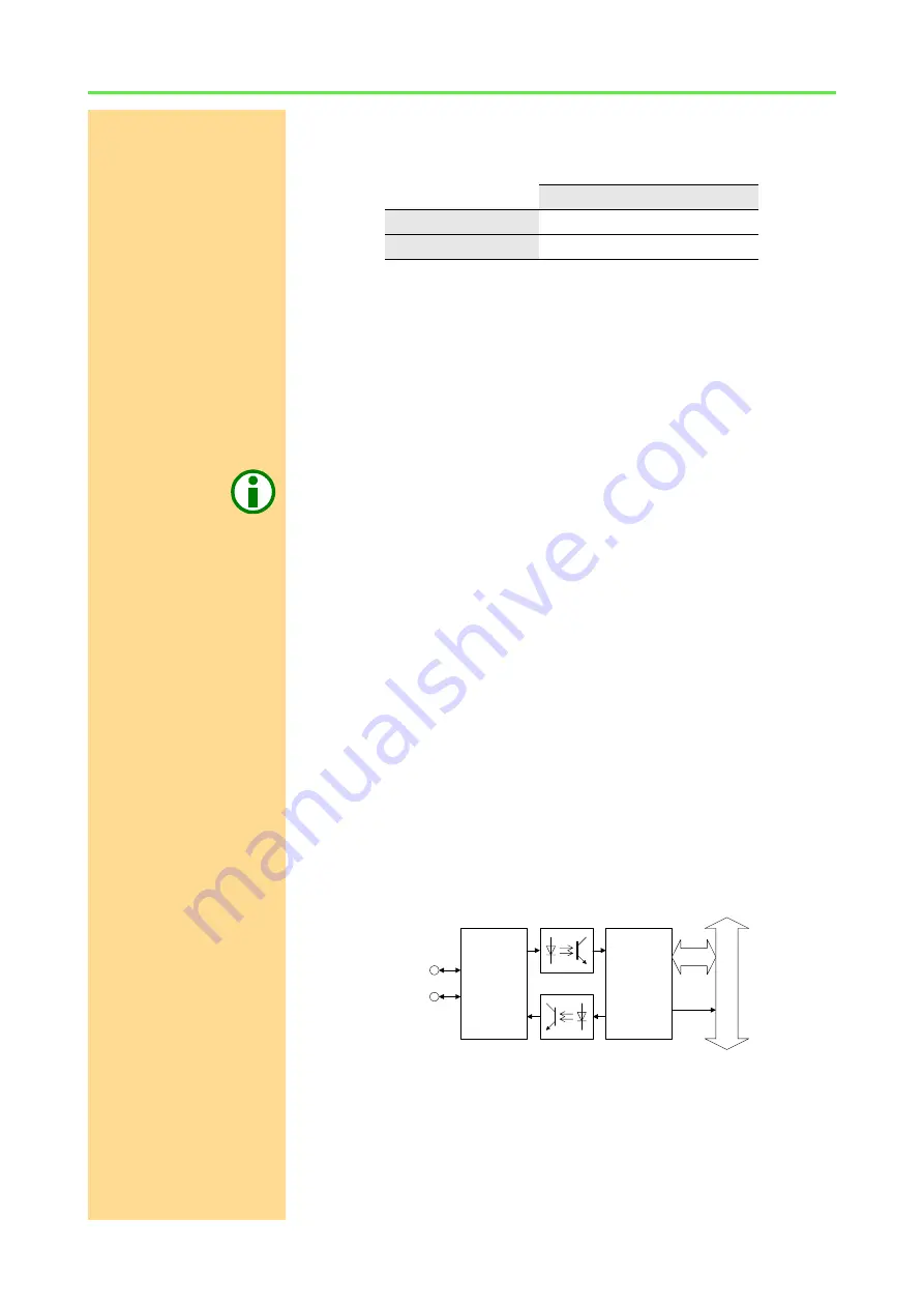
is galvanically isolated by optocouplers from the
ADwin
system.
An arriving message can trigger an interrupt which instantaneously generates
an event at the processor. Therefore an immediate processing of messages is
guaranteed.
The manual is divided into the following sections:
–
–
–
–
–
–
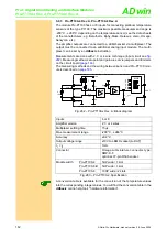
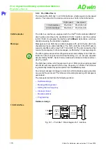
Hardware design
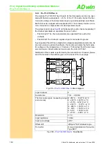
1 CAN interface
Fig. 301 – Pro-CAN-1: Block diagram for 1 interface
High speed
Low speed
1 CAN interface
Pro-CAN-1
Pro-CAN-1-LS
2 CAN interfaces
Pro-CAN-2
Pro-CAN-2-LS
ADwin-P
ro
bus
+
-
CAN
H
CAN-
controller
(intel 82527)
EVENT
CAN-
Trans-
ceiver
(82C250)
CAN
L
Data

