Pro I: Digital-I/O- and Counter Modules
Pro-CNT-VR4 (-L) Rev. A
ADwin
104
ADwin-Pro
Hardware, manual version 2.9, June 2006
5.8.6 Pro-CNT-VR4 (-L) Rev. A
To this module you find an improved successor module
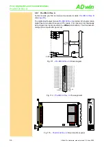
The Pro-CNT-VR4 Rev. A counter module has 4 up/down counters (32 bit), an
edge evaluation circuit, and a register (latch) for read out during the count pro-
cess. All counter values can be loaded (latched) into the register simulta-
neously with instruction
CNT_LATCH
. It is also possible to latch the counters
individually.
Each counter has 2 inputs which are decoded internally by an edge evaluation
logic (quadruple evaluation). The maximum frequency is 1.25MHz at each
input A and B (maximum internal count rate: 5MHz). Optionally the counters
can be used with one clock input and a direction input at a maximum count rate
of 10MHz. The operating mode is selectable by software, for each counter indi-
vidually.
According to the mode of operation, either the inputs A/B are active or the
inputs CLK/DIR.
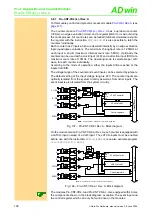
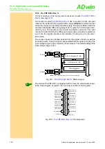
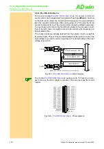
Fig. 191 – Pro-CNT-VR4 Rev. A: Block diagram
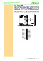
The module Pro-CNT-VR4 Rev. A is also available as Pro-CNT-VR4-L Rev. A
version. With this version each counter is equipped with a LATCH-input instead
of a CLR-input. The LATCH-inputs must be enabled before use with the
instruction
EXTLCH_ENABLE
.
(see also example program
<Pro-CNT-VR4-L-I.BAS>
).
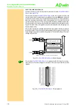
Fig. 192 – Pro-CNT-VR4-L Rev. A: Block diagram
The modules Pro-CNT-VR4 Rev. A and Pro-CNT-VR4-L Rev. A are equipped
with 4 times the components shown in the block diagram; exception: the event
input and the control register, which can only be found once on the modules.
NOTE:
Only Counter #1 is shown for clarity of the schematic.
Control registers
32 bit Counter #1
32 bit Latch #1
CLK
EN
CLR
A
ADwi
n
-P
ro
bus
B
CLR
DIR
DIR
CLK
DIR
EVENT
10k
10k
10k
10k
10k
10k
Note:
Only Counter #1 is shown for clarity of the schematic.
Control registers
32 bit Counter #1
32 bit Latch #1
CLK
EN
CLR
A
ADwi
n
-P
ro
bus
B
LATCH
DIR
DIR
EVENT
G
5 MHz
"Up"
CNT
_S
E
T
M
O
DE
10k
10k
10k
10k


