Pro I: Digital-I/O- and Counter Modules
Pro-CNT-VR4(-L)-I Rev. A
ADwin
106
ADwin-Pro
Hardware, manual version 2.9, June 2006
5.8.7 Pro-CNT-VR4(-L)-I Rev. A
To this module you find an improved successor module
(see
The counter module
has 4 up/down counters
(32 bits), an edge evaluation circuit, and a register (latch) for read out during
the count process. All count rates can be loaded (latched) simultaneously into
the register with the instruction
CNT_LATCH
. It is also possible to latch the
counters individually.
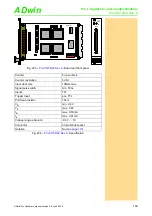
Each counter has 2 inputs which are decoded internally by an edge evaluation
logic (quadruple evaluation). The maximum throughput rate is 1.25MHz at
each input A and B (maximum internal count rate: 5MHz). Optionally the
counters can be used with a clock input (CLK) and a direction input (DIR) at a
maximum count rate of 10MHz. The operating mode is selectable per soft-
ware, for each counter individually.
According to the mode of operation, either the inputs A/B are active or the
inputs CLK/DIR.
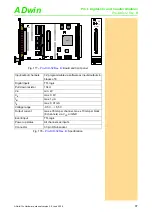
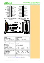
The voltage range of the counter and event inputs can be selected by jumpers.
The default setting of the input voltage range is 24V. The counter inputs are
optically isolated from the system circuitry as well as from other inputs. The
event input is also isolated from the system circuitry.
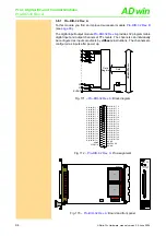
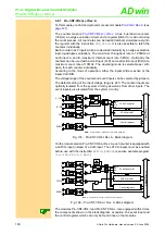
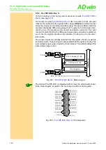
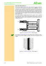
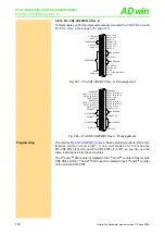
Fig. 197 – Pro-CNT-VR4-I Rev. A: Block diagram
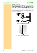
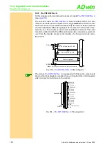
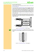
On the module version Pro-CNT-VR4-L-I Rev. A each counter is equipped with
a LATCH-input instead of a CLR-input. The LATCH-inputs must be enabled
before use with the instruction
EXTLCH_ENABLE
(see also example program
<Pro-CNT-VR4-L-I.BAS>
).
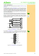
Fig. 198 – Pro-CNT-VR4-L-I Rev. A: Block diagram
The modules Pro-CNT-VR4-I and Pro-CNT-VR4-L-I are equipped with 4 times
the components shown in the block diagram; exception: the event input and
the control register, which can only be found once on the modules.
NOTE:
Only Counter #1 is shown for clarity of the schematic.
Control registers
32 bit Counter #1
32 bit Latch #1
CLK
EN
CLR
ADwin-
Pr
o
bu
s
DIR
DIR
+
-
A / CLK
24V
12V
5V
+
-
B / DIR
24V
12V
5V
+
-
CLR
24V
12V
5V
+
-
EVENT
24V
12V
5V
4k3
2k
560
4k3
2k
560
4k3
2k
560
4k3
2k
560
Note:
Only Counter #1 is shown for clarity of the schematic.
Control registers
32 bit Counter #1
32 Bit Latch #1
CLK
EN
CLR
ADwin-
P
ro
bus
DIR
DIR
+
-
A
24V
12V
5V
+
-
B
24V
12V
5V
+
-
LATCH
24V
12V
5V
+
-
EVENT
24V
12V
5V
G
5 MHz
"Up"
CNT
_S
E
T
M
O
DE
4k3
2k
560
4k3
2k
560
4k3
2k
560
4k3
2k
560


