Pro I: Analog Input Modules
Pro-AIn-8/14 Rev. A
ADwin
44
ADwin-Pro
Hardware, manual version 2.9, June 2006
5.5.3 Pro-AIn-8/14 Rev. A
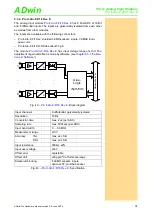
The analog input module
has a 14 bit ADC and 8 single
ended inputs. A programmable amplifier (PGA) and a multiplexer (MUX) are
connected before the ADC. The module can be combined with Pro-TC and
Pro-PT modules.
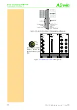
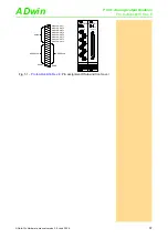
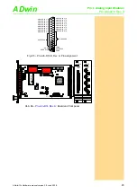
The inputs are available with the following connectors:
– Pro-AIn-8/12: shielded LEMO-sockets, CAMAC European norm.
– Pro-AIn-8/12-D: DSub socket 37-pin.
The module
is an advanced development of the module
with an input voltage range of ± 10V and a gain, program-
mable by software of 1, 2, 4 or 8. The adjustment of gain and offset is made
by software (see
chapter 6.3.1 "Calibration per Software"
).
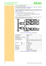
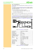
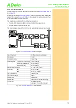
The module includes a sequence control, which may read the measurement
values of all input channel sequentially.
Fig. 63 –
: Block diagram
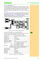
Input channels
8 differential via multiplexer
Resolution
14 bit
Conversion time
max. 0.5µs
Sampling rate
max. 2000ksps
Multiplexer settling time
3µs
Measurement ranges
±10V, optional: ±20mA / 8 channels
Gain
1, 2, 4, 8 software selectable
Accuracy
INL
typ. ±0.6 LSB, max. ±2 LSB
DNL
typ. ±0.3 LSB, max. ±1 LSB
With the option ±20mA there is an additional inaccuracy of
0.05% of the measured voltage (by the 500
Ω
shunt).
Input resistance
330k
Ω
, ±2%
Input over-voltage
±35V
Offset error
adjustable
Offset drift
±30 ppm/ºC
Connector
8 LEMO sockets
optional: 37-pin DSub socket
Fig. 64 –
: Specification
ADwi
n
-P
ro
bus
A
D
MUX
1
330k
330k
2
330k
330k
8
330k
330k
. . . . . .
Addr.
Data
Data
Registers
Address
Decoder
Data
PGA
Vu= 1, 2, 4, 8
. . . . .
Sequence
Control
Control

