Pro I: Digital-I/O- and Counter Modules
Pro-PWM-4 Rev. A
ADwin
132
ADwin-Pro
Hardware, manual version 2.9, June 2006
5.8.20 Pro-PWM-4 Rev. A
The output module
generates pulse width modulated sig-
nals (PWM signals) at four outputs. Each (PWM) signal can be configured indi-
vidually via software; that means, they can be configured separately.
The function of the module is significantly characterized by its 4 counters
(16 bit) and 8 registers (16 bit), 4 for the duration of the low voltage level and
4 for the high voltage level.
The counters are clocked by a crystal oscillator with a fixed frequency of 5MHz.
This frequency can roughly be prescaled in 2
n
steps (0 < n < 7, n
∈
N). The
prescaling in conjunction with the duration of the high and low time defines the
output frequency of the PWM signals. The output of the PWM signals is
attained by evaluating the register values and the counter values via an
RS-flip-flop.
By setting a register, the counters can be enabled or disabled. But do not con-
fuse this with enabling or disabling the PWM output (putting it into a "static"
mode). This can only be made by the command
PWM_OUT()
, which sets the
output to a defined status, when the counter is enabled.
The lowest output frequency at a still definable duty cycle of approx. 0...100%
is about 0.6Hz.
The highest output frequency where the duty cycle can be still defined in
1%-steps, is 50kHz.
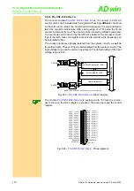
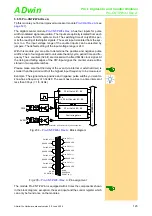
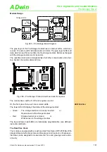
The module Pro-PWM-4 is equipped with 4 times the components shown in the
block diagram; exception: the event input and the 5MHz reference oscillator,
which can only be found once on each module.
Fig. 254 –
Fig. 253 –
: Block diagram
Data
Data
A B
A B
NOTE:
Only PWM-output #1 is shown for clarity of the schematic. The 5MHz clock signal is distributed to all prescalers.
G
5 MHz
Prescaler #1
divide by 2
n
(n = 0...7)
Control registers #1
16 bit HIGH-time Register #1
16 bit Counter #1
16 bit LOW-time Register #1
Q
Q
S
R
B
A
A
B
EN
EN
CLK
EN
CLR
PWM #1
ADw
in
-P
ro
bu
s
Data
Data
Data
Data
to other
Prescaler
Data
EVENT
10k
DGND
EVENT IN
PWM OUTPUT 1
PWM OUTPUT 2
PWM OUTPUT 3
PWM OUTPUT 4
RESERVED
DGND
RESERVED
DGND
19
18
17
16
15
14
13
12
11
10
9
8
7
6
5
4
3
2
1
37
36
35
34
33
32
31
30
29
28
27
26
25
24
23
22
21
20
RESERVED
RESERVED
RESERVED
RESERVED
RESERVED

