ADwin-Pro
Hardware, manual version 2.9, June 2006
121
Pro I: Digital-I/O- and Counter Modules
Pro-CNT-PW4 Rev. A
ADwin
5.8.15 Pro-CNT-PW4 Rev. A
To this module you find an improved successor module
).
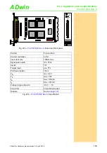
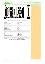
The digital counter module
has four inputs for pulse
width modulated signal acquisition. With this module you are able to determine
the positive and negative pulse widths, the duty cycle, period time, and fre-
quency. The 4 counters (32 bit) are clocked with a fixed 5MHz clock signal. At
the rising and falling edges of the PW-input signal, the counter value will be
stored in two separate latches.
Please, make sure that the delay of the event (via internal or external timer) is
shorter than the period width of the highest input frequency to be measured.
Example: The signal whose positive and negative pulse widths you want to
know has a frequency of 3.3kHz. The event has to arrive in a time interval of
less than 303µs (= 1/3.3kHz).
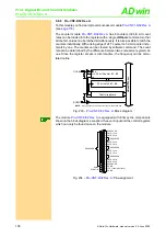
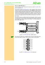
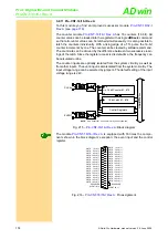
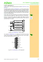
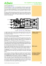
Fig. 229 –
: Block diagram
The module
is equipped with 4 times the components
shown in the block diagram, exception: the event input and the control register
which can only be found once on the modules.
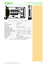
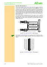
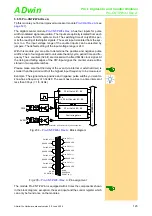
Fig. 230 –
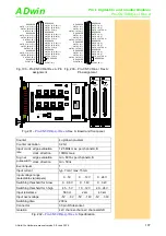
: Pin assignment
NOTE:
Only Counter #1 is shown for clarity of the schematic.
Control registers
32 bit Counter #1...#4
32 bit Latch #5...#8
CLK
EN
CLR
ADwi
n
-P
ro
bus
PW #n
EVENT
32 bit Latch #1...#4
G
5 MHz
10k
10k
DGND
EVENT IN
PW INPUT 1
PW INPUT 2
PW INPUT 3
PW INPUT 4
RESERVED
DGND
+5V, <100mA (unfused)
DGND
19
18
17
16
15
14
13
12
11
10
9
8
7
6
5
4
3
2
1
37
36
35
34
33
32
31
30
29
28
27
26
25
24
23
22
21
20
RESERVED
RESERVED
RESERVED
RESERVED
RESERVED

