ADwin-Pro
Hardware, manual version 2.9, June 2006
187
Pro I: Signal Conditioning and Interface Modules
Pro-RSxxx Rev. A
ADwin
Printed circuit board,
front panels
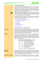
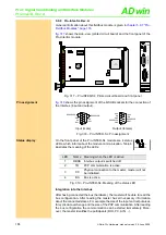
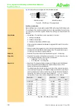
shows the side-view (printed circuit boad) and the front panel of the
modules Pro-RS232-x and Pro-RS485-x.
Fig. 323 – Pro-RSxxx: Printed circuit board and front panels
Pro-RS-485-2
Pro-RS-485-4
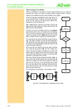
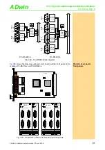
Fig. 322 – Pro-RS485: Block diagrams
AD
win
-P
ro
bus
Quad-
UART
(Texas
Instruments,
TL16C754)
Data
G
36.864 MHz
Addr.
1
6
RS-485-
Transceiver
(LTC485)
2
7
3
HIGH
8
LOW
4
9
5
SGND
1
6
RS-485-
Transceiver
(LTC485)
2
7
3
HIGH
8
LOW
4
9
5
SGND
RS-
4xx
#1
RS-
4xx
#2
Ch#1
Ch#2
AD
win
-P
ro
bu
s
Quad-
UART
(Texas
Instruments,
TL16C754)
Data
G
36.864 MHz
Ch#1
Ch#2
Ch#3
Ch#4
Addr.
1
6
RS-485-
Transceiver
(LTC485)
2
7
3
HIGH
8
LOW
4
9
5
SGND
1
6
RS-485-
Transceiver
(LTC485)
2
7
3
HIGH
8
LOW
4
9
5
SGND
1
6
RS-485-
Transceiver
(LTC485)
2
7
3
HIGH
8
LOW
4
9
5
SGND
1
6
RS-485-
Transceiver
(LTC485)
2
7
3
HIGH
8
LOW
4
9
5
SGND
RS-
4xx
#1
RS-
4xx
#2
RS-
4xx
#3
RS-
4xx
#4
19RS232A
TL16C754
OCX
36.864
LS19
LT
1137
LT
1137
RS-xxx #1
RS-xxx #2
ON
DIP
1
2
3
4
5
6
7
8
FPGA
RS-485-2
SERIAL PORT
1
2
RS485-4
SERIAL PORT
1
2
3
4
RS-232-2
SERIAL PORT
1
2
RS232-4
SERIAL PORT
1
2
3
4


