ADwin-Pro
Hardware, manual version 2.9, June 2006
71
Pro I: Analog Input Modules
Pro-AIn-F-8/14 Rev. B
ADwin
5.5.16 Pro-AIn-F-8/14 Rev. B
Analog input module
with 8 fast-ADC (14 bit) and 8 dif-
ferential inputs.
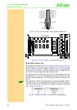
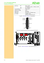
The inputs are available with the following connectors:
– Pro-AIn-4/14: shielded LEMO-sockets, CAMAC European norm.
– Pro-AIn-4/14-D: DSub socket 37-pin.
The module has 2 operating modes, which you can use optionally for each of
the channels:
– Standard single measurement: Upon each process call a single mea-
surement can be executed by starting the conversion (waiting for its
end), by reading out the measurement values and if necessary by pro-
cessing them.
– Start of a burst measurement sequence: Upon each process call a com-
plete measurement sequence, which consists of a large number of indi-
vidual measurements, is started. The module executes the
measurement sequence alone, independent of the
ADwin
system.
The measurement values - number and measurement frequency are to be
defined in the program - are stored in a special burst memory of the module,
which enables measurement frequencies of up to 2MHz. The size of the burst
memory limits the number of measurement values or the total time of the mea-
surement.
Only after end of the measurement sequence will you be able to read out the
stored measurement values from the burst memory and process them.
During a single measurement the processor of the
ADwin-Pro
system is
checking the sequence of each individual measurement, whereas during a
burst measurement it is the input module which is checking the measurement
sequence.
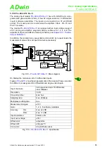
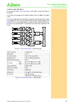
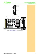
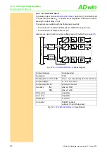
Fig. 126 –
: Block diagram
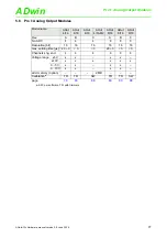
Input channels
8 differential
Resolution
14 bit
Conversion time
max. 0.4µs (per ADC)
Sampling rate
max. 2200ksps (per ACDC)
Memory size
2
20
-1 = 1048575 meas. values total
Measurement ranges
±10V
Fig. 127 –
: Specification
Da
ta
A
dr
esse
AD
wi
n-
P
ro
bu
s
A
D
1
100k
100k
2
100k
100k
8
100k
100k
Addr.
Data
Buffer
+
-
A
D
Buffer
+
-
A
D
Buffer
+
-
. . . .
.
. . .
. .
. . . .
.
Data
PGA
G = 1, 2, 4, 8
+
-
PGA
G = 1, 2, 4, 8
+
-
PGA
G = 1, 2, 4, 8
+
-
Glue-
Logic
(Adress-Dekodierung,
Ablaufsteuerung,
SRAM-Steuerung)
SRAM


