ADwin-Pro I
ADwin
6
ADwin-Pro
Hardware, manual version 2.9, June 2006
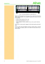
Fig. 3 – Enclosure
ADwin-Pro II
(up from Rev.
Please note that modules for Pro I bus (grey in
) and for Pro II bus have
different plug-in positions. You recognize the right position easily by the color
of the bearings:
– White bearings: Modules for Pro II bus.
– Black bearings: Modules for Pro I bus.
Output modules Pro-AOut-x with Rev. A may not be used for technical
reasons.
The processor module must be plugged-in at the middle position (white bear-
ings).
There is a gap of half a slot between processor module and Pro I modules
(cover plates accompanied), while Pro II modules fit directly besides the pro-
cessor module.
7
4
5
6
1
2
3
14
11 12 13
8
9
10
15
POWER
ADwin-
Pro II
8
6
4
1
2
3
5
7
9
10 11 12 13
CPU-T11
ADwin-Pro
DIG I/O 0
EVENT IN
ST
BU
AC
LI
ET
HE
RN
ET
DIG I/O 1
Modules for Pro II-Bus
Modules for Pro II-Bus
Modules for Pro I-Bus
Modules for Pro I-Bus


