ADwin-Pro
Hardware, manual version 2.9, June 2006
165
Pro I: Signal Conditioning and Interface Modules
Pro-PT100-4 Rev. A, Pro-PT100-8 Rev. A
ADwin
Measurement Method
You can choose one of three Measurement methods:
,
or
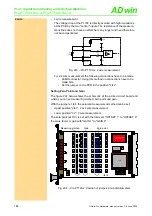
2 wire
– 2 wire measurement
Please pay attention to a very short connection with low impedance be-
tween the Pt 100 and the module input, because the voltage drop gets
added to the measured voltage.
This is the reason why this measurement method is in general not to be
recommended for precise measurements.
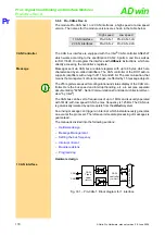
Fig. 291 – Pro-PT100-x: 2 wire measurement
For a 2 wire measurement the following connections have to be made:
• LEMO connector: Connect "", pin 4 with "", pin 1.
• LEMO connector: Connect "source -", pin 3 with "sensor -", pin 2.
• Set the jumper on the PCB to the position "2/4L".
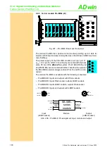
3 wire
– 3 wire measurement
In order to avoid the disadvantages of the 2 wire measurement, the volt-
age drop in the measurement lines is here compensated by a second
voltage source I2.
To keep the measurement error as small as possible, the resistance val-
ue of the three measurement lines from the Pt 100 to the module input
should be identical.
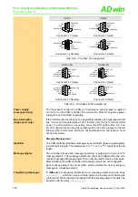
Fig. 292 – Pro-PT100-x: 3 wire measurement
For a 3 wire measurement the following connections have to be made:
• LEMO connector: Connect "", pin 4 with "", pin 1.
• Set the jumper on the PCB to the position "3L", in order to activate
the second voltage source.
InAmp
G = 50
+
-
4
1
Sense +
3
Source -
2
Sense -
Pt
100
+Ub
I
1
R1
R2
C1
C2
ν
InAmp
G = 50
+
-
4
1
Sense +
3
Source -
2
Sense -
Pt
100
+Ub
I
1
R1
R2
C1
C2
ν
I
2
3L


