ADwin-Pro
Hardware, manual version 2.9, June 2006
141
Pro I: Digital-I/O- and Counter Modules
Pro-Storage Rev. A
ADwin
Module Design
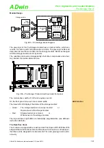
Fig. 265 – Pro-Storage: Block Diagram
The glue-logic of the Pro-Storage module has an internal buffer, which can
receive 12 sectors with 128 data words à 32-bits. The glue-logic buffers all
data, which is read from or written into the storage medium. Data is exchanged
with the storage medium sector by sector.
The real-time clock works independently of all other components and is bat-
tery-backed. It provides date and time.
Fig. 266 – Pro-Storage: Printed circuit board and front panel
The module has a width of 1 HP and requires one slot.
LED function
On the front panel there are 3 two-colored LEDs.
The lower left LED displays the status of the storage medium:
The top and lower right LEDs are individually programmable. (see
ADbasic
instruction
SETLED
).
The Real-Time Clock
The module is equipped with a real-time clock from Epson RTC-4553AA. With
simple
ADbasic
instructions, date and time are set and read out, so that a spec-
ified time can be assigned to measurements. Time and glue-logic work auton-
omously.
data
ADwi
n-Pro
bus
address
Glue-Logic
(address decoding, timing-
control, RAM controlling)
RAM
1536 x 32 bit
data
address
control
R
eal
T
ime
C
lock
da
ta
a
ddr
ess
1.8"
HDD
PCMCIA
slot
Type II
PC Card
CF
card
CF
adapter
back-up
battery
Storage media
19DIOMEM02
A0 A1 A2 A3 A4 A5 A6 A7
OCX
40MHz
LM3940
-3.3
XILINX
SPARTAN
XC2S150
LM3937
-2.5
AD
M
70
6
AD
M
70
6
ON
DIP
1
2
3
4
5
6
7
8
7S
08
B
R4553
3V
Lithium
CR1632
+
+3V
CR1632
STORAGE
R/W
– Green:
The storage medium is correctly inserted
or
Read access to the storage medium
– Red:
Storage medium is removed
or
Write access to the storage medium


