Pro I: Digital-I/O- and Counter Modules
Pro-CNT-16/32-I Rev. A
ADwin
118
ADwin-Pro
Hardware, manual version 2.9, June 2006
5.8.13 Pro-CNT-16/32-I Rev. A
The counter module
has 16 counters (32 bit). All
counter values can be loaded into the register with a single
ADbasic
command
so that all counter values can be latched simultaneously. It is also possible to
latch the counters individually. With a rising edge of a TTL pulse the 32-bit
counter increments by one. The counter can be cleared by software command.
The count rate can be derived by the difference between two successive read-
ings of the latch. Since the register access is discrete-time, the frequency can
be calculated online.
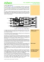
The counter inputs are optically isolated from the system circuitry as well as
from other inputs. The event input is also isolated from the system circuitry. The
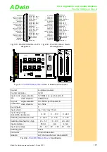
input voltage range can be selected by jumpers. The default setting of the input
voltage range is 24V.
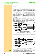
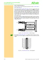
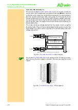
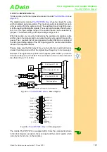
: Block diagram
The module
is equipped with 16 times the compo-
nents shown in the block diagram, exception: the event input and the control
register.
Fig. 224 –
NOTE:
Only Counter #1 is shown for clarity of the schematic.
Control registers
32 bit Counter #1...#16
32 bit Latch #1...#16
CLK
EN
CLR
ADwi
n
-P
ro
bus
+
-
CLK #n
24V
12V
5V
+
-
EVENT
24V
12V
5V
4k3
2k
560
4k3
2k
560
CNTR 1 CLK (-)
CNTR 5 CLK (-)
CNTR 9 CLK (-)
CNTR 13 CLK (-)
CNTR 2 CLK (-)
CNTR 6 CLK (-)
CNTR 10 CLK (-)
CNTR 14 CLK (-)
CNTR 3 CLK (-)
CNTR 7 CLK (-)
CNTR 11 CLK (-)
CNTR 15 CLK (-)
CNTR 4 CLK (-)
CNTR 8 CLK (-)
CNTR 12 CLK (-)
CNTR 16 CLK (-)
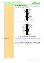
RESERVED
EVENT IN (+)
CNTR 1 CLK (+)
CNTR 5 CLK (+)
CNTR 9 CLK (+)
CNTR 13 CLK (+)
CNTR 2 CLK (+)
CNTR 6 CLK (+)
CNTR 10 CLK (+)
CNTR 14 CLK (+)
CNTR 3 CLK (+)
CNTR 7 CLK (+)
CNTR 11 CLK (+)
CNTR 15 CLK (+)
CNTR 4 CLK (+)
CNTR 8 CLK (+)
CNTR 12 CLK (+)
CNTR 16 CLK (+)
EVENT IN (-)
19
18
17
16
15
14
13
12
11
10
9
8
7
6
5
4
3
2
1
37
36
35
34
33
32
31
30
29
28
27
26
25
24
23
22
21
20
RESERVED


