ADwin-Pro
Hardware, manual version 2.9, June 2006
31
Pro II: Analog Input Modules
Pro II-AIn-F-8/18 Rev. E
ADwin
5.3.4 Pro II-AIn-F-8/18 Rev. E
The analog input module
Pro II-AIn-F-8/18 Rev. E
has 8 Fast-ADC of 18 Bit
and 8 differential inputs. The inputs are galvanically isolated from each other
as well as from other modules.
The inputs are available with the following connectors:
– Pro II-AIn-F-8/18-L2: shielded LEMO-sockets, 2-pole, CAMAC Euro-
pean norm.
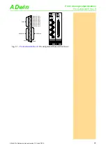
– Pro II-AIn-F-8/18-D: DSub socket 37-pin.
The module
Pro II-AIn-F-8/18 Rev. E
has input voltage range of ±10V. The
adjustment of gain and offset is made by software. (see
).
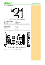
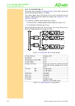
Fig. 42 –
Pro II-AIn-F-8/18 Rev. E
: Block diagram
Input channels
8 differential, galvanically isolated
Resolution
18 Bit
Conversion time
max. 2µs (per ADC)
Sampling rate
max. 500ksps (per ADC)
Input band width
0 … 0.6MHz
Measurement range
±10V
Accuracy
INL
max. ±4 LSB
DNL
max. ±3 LSB
Input resistance
330k
Ω
, ±2%
Input over-voltage
±35V
Offset error
adjustable
Offset drift
±30ppm/ºC of full scale range
Steckerverbindung
8 LEMO sockets, 2-pole
optional: 37-pin DSub socket
Fig. 43 –
Pro II-AIn-F-8/18 Rev. E
: Specification
AD
w
in
-P
ro
I
I
bu
s
1
330k
8
Addr.
Data
Glue-
Logic
(address decoder,
sequence control)
A
D
Buffer
+
-
A
D
Buffer
+
-
330k
.
.
.
.
.
.
.
.
.
.
.
.
.
.
.
.
.
.
.
.
.
.
.
.

