ADwin-Pro
Hardware, manual version 2.9, June 2006
41
Pro I: Analog Input Modules
Pro-AIn-8/12 Rev. A
ADwin
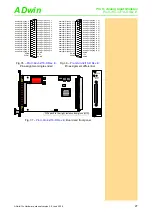
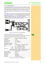
Fig. 54 – Pro-AIn-8/12-D Rev. A: Pin assignment
Setting the Input Voltage Range
is equipped with an ADC whose input
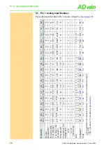
voltage range is adjustable by 2 jumpers. As a default setting, the ADC is set
to the voltage range of ±10V. The settings for other voltage ranges can be
found in
.
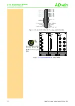
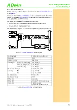
Fig. 55 –
: Board and front panel
After every jumper setting you have to recalibrate the ADC, in order to assure
correct measurement results. The individual steps are described in the
).
For the accurate adjustment of offset and gain the potentiometers UPO (uni-
polar) or BPO (bipolar) as well as GAIN are available (
ANALOG IN 1 (-)
ANALOG IN 2 (-)
ANALOG IN 3 (-)
ANALOG IN 4 (-)
ANALOG IN 5 (-)
ANALOG IN 6 (-)
ANALOG IN 7 (-)
ANALOG IN 8 (-)
AGND
RESERVED
ANALOG IN 1 (+)
ANALOG IN 2 (+)
ANALOG IN 3 (+)
ANALOG IN 4 (+)
ANALOG IN 5 (+)
ANALOG IN 6 (+)
ANALOG IN 7 (+)
ANALOG IN 8 (+)
AGND
RESERVED
DGND
19
18
17
16
15
14
13
12
11
10
9
8
7
6
5
4
3
2
1
37
36
35
34
33
32
31
30
29
28
27
26
25
24
23
22
21
20
RESERVED
RESERVED
19AD774
FPGA
FPGA
ON
1 2 3 4 5 6 7 8
A0 A1 A2 A3 A4 A5 A6 A7
LS19
M
P
C
507
DC/DC-converter
P
G
A
203
ADS774
10V
UNI
UP
O
GA
IN
BP
O
20V
BI
P
AIN8/12
ANALOG
INPUT
1
2
3
4
5
6
7
8
AIN8/12
ANALOG
INPUT
Jumpers
Potentiometers
Voltage range
J1
J2
±5V bipolar
BIP
10V
±10V bipolar
(default)
BIP
20V
0...10V unipolar
UNI
10V
not allowed
UNI
20V
:
Jumper positions for the input
voltage range
Potenti-
ometer
Adjustment of
Gain
Gain factor
BPO
Offset (bipolar setting)
UPO
Offset (unipolar setting)
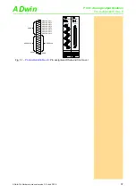
Fig. 57 –
: Function
of the potentiometers

