ADwin-Pro
Hardware, manual version 2.9, June 2006
91
Pro I: Analog Input and Output Modules
Pro-AO-16/8-12 Rev. A
ADwin
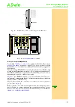
Setting the Input and Output Voltage Range
The 12 bit input/output module
is equipped with 1 ADC
and 8 DAC. The input voltage range of the ADC and the output voltage range
of the DAC can be set by 3 jumpers each. The default settings of the ADC as
well as of the DAC is the voltage range ±10V.
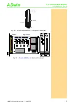
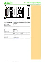
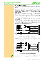
Fig. 166 –
: Board and front panel
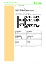
ADC
Input channels
16 single-ended via multiplexer
Resolution
12 bit
Conversion time
7.5µs
Measurement ranges
0…10V, ±5V, ±10V; optional 0…20mA
Gain
1, 2, 4, 8 software selectable
Accuracy
INL
max. ±1 LSB
DNL
max. ±1 LSB
Input resistance
100k
Ω
, ±2%
Input over-voltage
±35V
Offset error
adjustable
Offset drift
±30 ppm/ºC of full scale range
DAC
Output channels
8 single-ended
Resolution
12 bit
Settling time to 0.01%
10µs for a full scale step
Output voltage
0…10V, ±5V, ±10V
Output current max.
5mA per channel
Accuracy
INL
max. ±1 LSB
DNL
max. ±1 LSB
Offset error
adjustable
Gain error
adjustable
Offset drift
±10µv/ºC
Common
Connector
37-pin DSub socket
Fig. 165 –
: Specification
19DA8413
ON
1 2 3 4 5 6 7 8
A0 A1 A2 A3 A4 A5 A6 A7
LS19
M
P
C
506
PGA203
ADS774
FP
G
A
FP
G
A
OCX
DC/DC-converter
T
L034
T
L034
DAC
8413
DAC
8413
102
105
102
105
102
105
102
105
0-10V
±5V
±10V
O1-4
G1-4
O5-8
G5-8
10V
20V
UNI
BIP
UP
O
BP
O
GA
IN
AO16/8-12
ANALOG
IN-/OUTPUT
Jumpers / potentiometers for outputs
Potentiometers for inputs
Jumpers for inputs

