Pro I: Digital-I/O- and Counter Modules
Pro-CO4-D Rev. A
ADwin
130
ADwin-Pro
Hardware, manual version 2.9, June 2006
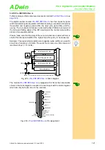
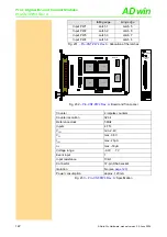
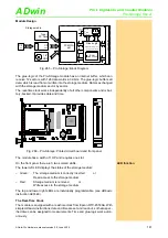
DIP switch on the module (component side, middle)
You can determine slow and fast input signals with high measurement rate
without switching, by connecting 1 counter input with 2 counters. For this you
have to change the DIP switch positions on the module:
– Switch counter 3 (additionally to counter 1) to counter input 1:
Push the switches of the
upper
double DIP switches upwards.
– Switch counter 4 (additionally to counter 2) to counter input 2:
Push the switches of the
lower
double-DIP switches upwards.
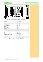
Fig. 249 –
: Board and front panel
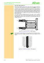
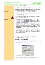
The figure below illustrates the DIP switch positions and the resulting
input-counter-connections.
Program one of the two counters with CLK and DIR signal inputs (up/down
counter), the other with PWM-input (PWM analysis). In a corresponding
ADba-
sic
process you can now determine the frequency or period duration of the sig-
nal in a wide frequency range.
DIP switch
position
Input counter#
A/CLK/PWM
Counter
CNTR-#1 CNTR-#2 CNTR-#3 CNTR-#4
1
9
-
-
-
2
-
9
-
-
3
-
-
9
-
4
-
-
-
9
1
9
-
9
-
2
-
9
-
-
3
-
-
-
-
4
-
-
-
9
1
9
-
-
-
2
-
9
-
9
3
-
-
9
-
4
-
-
-
-
Fig. 250 –
: Allocation of Input to Counter with DIP switches
19DIOCNT201
A0 A1 A2 A3 A4 A5 A6 A7
OCX
40MHz
AT17LV010
LT
C
485
LM3940-3.3
MA
X
3098
XILINX
SPARTAN
XC2S150
LM3937-2.5
AD
M
706
AD
M
706
ON
DIP
1
2
3
4
5
6
7
8
MA
X
3098
MA
X
3098
MA
X
3098
LT
C
485
LT
C
485
LT
C
485
7S
08B
CLK/PWM-#1
Ö
CNTR-#1 & #3
CLK/PWM-#1
Ö
CNTR-#1
CLK/PWM-#2
Ö
CNTR-#2 & #4
CLK/PWM-#2
Ö
CNTR-#2
CO4-D
COUNTER
INPUT
DIP-switches


