Pro I: Signal Conditioning and Interface Modules
Pro-PT100-4 Rev. A, Pro-PT100-8 Rev. A
ADwin
166
ADwin-Pro
Hardware, manual version 2.9, June 2006
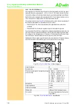
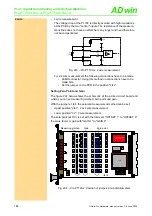
4 wire
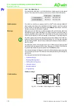
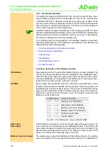
– 4 wire measurement
The voltage drop at the Pt 100 is directly avoided with high impedance
at the PCB by the two "sensor" inputs. The resistance of the measure-
ment lines does not have an effect here any longer and need therefore
not be compensated.
Fig. 293 – Pro-PT100-x: 4 wire measurement
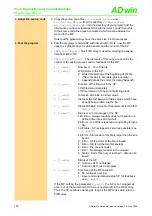
For a 4 wire measurement the following connections have to be made:
• LEMO connector: Using this method no connections have to be
made here.
• Set the jumper on the PCB to the position "2/4L".
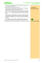
Setting Zero Point and Gain
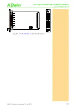
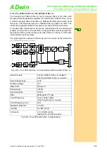
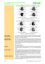
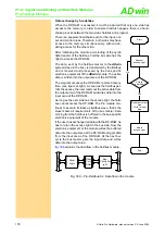
below shows the schematic of the printed circuit board and
where you can set measuring method, zero point and gain.
With the jumpers 1 to 8 the selected measurement method can be set:
– Upper position "2/4L": 2 or 4 wire measurement
– Lower position "3L": 3 wire measurement
The zero point (at 0°C) is set with the trimmers "OFFSET 1" to "OFFSET 8",
the scale factor or gain with "GAIN 1" to "GAIN 8".
Fig. 294 – Pro-PT100-x: Position of jumpers and potentiometers
InAmp
G = 50
+
-
4
1
Sense +
3
Source -
2
Sense -
Pt
100
+Ub
I
1
R1
R2
C1
C2
ν
19PT02
FPGA
ON
1 2 3 4 5 6 7 8
A0 A1 A2 A3 A4 A5 A6 A7
OPA
132U
MPC506AU
RE
F
102U
OP
A
2132U
2/4L
3L
INA
132U
OPA
27U
INA
118U
INA
132U
INA
132U
2/4L
3L
INA
132U
OPA
27U
INA
118U
INA
132U
INA
132U
2/4L
3L
INA
132U
OPA
27U
INA
118U
INA
132U
INA
132U
2/4L
3L
INA
132U
OPA
27U
INA
118U
INA
132U
INA
132U
2/4L
3L
INA
132U
OPA
27U
INA
118U
INA
132U
INA
132U
2/4L
3L
INA
132U
OPA
27U
INA
118U
INA
132U
INA
132U
2/4L
3L
INA
132U
OPA
27U
INA
118U
INA
132U
INA
132U
2/4L
3L
INA
132U
OPA
27U
INA
118U
INA
132U
INA
132U
GAIN 8
OFFSET 8
OFFSET 7
OFFSET 6
OFFSET 5
OFFSET 4
OFFSET 3
OFFSET 2
OFFSET 1
GAIN 7
GAIN 6
GAIN 5
GAIN 4
GAIN 3
GAIN 2
GAIN 1
8
7
6
5
4
3
2
1
DC/DC CONVERTER
IN 5V OUT ±15V / ±65mA
Measuring method
Gain
Zero point

