Spanning Tree Protocol |
1061
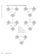
In STP topology 2 (
Figure 52-10
upper right), STP is enabled on device D on which a software bridge
application is started to connect to the network. Because the priority of the bridge in device D is lower than
the root bridge in Switch A, device D is elected as root, causing the link between Switches A and B to enter
a blocking state. Network traffic then begins to flow in the directions indicated by the BPDU arrows in the
topology. If the links between Switches C and A or Switches C and B cannot handle the increased traffic
flow, frames may be dropped.
In STP topology 3 (
Figure 52-10
lower middle), if the root guard feature is enabled on the STP port on
Switch C that connects to device D, and device D sends a superior BPDU that would trigger the election of
device D as the new root bridge, the BPDU is ignored and the port on Switch C transitions from a
forwarding to a root-inconsistent state (shown by the green X icon). As a result, Switch A becomes the root
bridge.
All incoming and outgoing traffic is blocked on an STP port in a root-inconsistent state. After the timeout
period, the Switch C port automatically transitions to a forwarding state as soon as device D stops sending
BPDUs that advertise a lower priority.
If you enable a root guard on all STP ports on the links where the root bridge should not appear, you can
ensure a stable STP network topology and avoid bridging loops.
Summary of Contents for Force10 E300
Page 1: ...FTOS Configuration Guide FTOS 8 4 2 7 E Series TeraScale C Series S Series S50 S25 ...
Page 32: ...32 w w w d e l l c o m s u p p o r t d e l l c o m ...
Page 132: ...132 802 1X w w w d e l l c o m s u p p o r t d e l l c o m ...
Page 310: ...310 Configuration Replace and Rollback w w w d e l l c o m s u p p o r t d e l l c o m ...
Page 330: ...330 Dynamic Host Configuration Protocol w w w d e l l c o m s u p p o r t d e l l c o m ...
Page 402: ...402 High Availability w w w d e l l c o m s u p p o r t d e l l c o m ...
Page 462: ...462 Interfaces w w w d e l l c o m s u p p o r t d e l l c o m ...
Page 482: ...482 IPv4 Addressing w w w d e l l c o m s u p p o r t d e l l c o m ...
Page 506: ...506 IPv6 Addressing w w w d e l l c o m s u p p o r t d e l l c o m ...
Page 582: ...582 Layer 2 w w w d e l l c o m s u p p o r t d e l l c o m ...
Page 642: ...642 Multicast Source Discovery Protocol w w w d e l l c o m s u p p o r t d e l l c o m ...
Page 662: ...662 Multiple Spanning Tree Protocol w w w d e l l c o m s u p p o r t d e l l c o m ...
Page 690: ...690 Object Tracking w w w d e l l c o m s u p p o r t d e l l c o m ...
Page 754: ...754 PIM Dense Mode w w w d e l l c o m s u p p o r t d e l l c o m ...
Page 784: ...784 PIM Source Specific Mode w w w d e l l c o m s u p p o r t d e l l c o m ...
Page 800: ...800 Power over Ethernet w w w d e l l c o m s u p p o r t d e l l c o m ...
Page 876: ...876 Quality of Service w w w d e l l c o m s u p p o r t d e l l c o m ...
Page 892: ...892 Routing Information Protocol w w w d e l l c o m s u p p o r t d e l l c o m ...
Page 1006: ...1006 Simple Network Management Protocol w w w d e l l c o m s u p p o r t d e l l c o m ...
Page 1018: ...1018 SONET SDH w w w d e l l c o m s u p p o r t d e l l c o m ...
Page 1048: ...1048 Broadcast Storm Control w w w d e l l c o m s u p p o r t d e l l c o m ...
Page 1096: ...1096 Uplink Failure Detection UFD w w w d e l l c o m s u p p o r t d e l l c o m ...
Page 1098: ...1098 Upgrade Procedures w w w d e l l c o m s u p p o r t d e l l c o m ...
Page 1196: ...1196 C Series Debugging and Diagnostics w w w d e l l c o m s u p p o r t d e l l c o m ...
Page 1252: ...1252 Standards Compliance w w w d e l l c o m s u p p o r t d e l l c o m ...
Page 1262: ...1262 Index w w w d e l l c o m s u p p o r t d e l l c o m ...


