background image

Artisan Technology Group 

is your source for quality 

new and certified-used/pre-owned equipment

• 

FAST SHIPPING AND 

DELIVERY

• 

TENS OF THOUSANDS OF 

IN-STOCK ITEMS

•  EQUIPMENT DEMOS
• 

HUNDREDS OF 

MANUFACTURERS 

SUPPORTED

•  LEASING/MONTHLY


RENTALS

•  ITAR CERTIFIED


SECURE ASSET 

SOLUTIONS

SERVICE CENTER REPAIRS

Experienced engineers and technicians on staff 

at our full-service, in-house repair center

WE BUY USED EQUIPMENT

Sell your excess, underutilized, and idle used equipment 

We also offer credit for buy-backs and trade-ins

www.artisantg.com/WeBuyEquipment


REMOTE INSPECTION

Remotely inspect equipment before purchasing with 

our interactive website at


www.instraview.com

LOOKING FOR MORE INFORMATION? 

Visit us on the web at


www.artisantg.com


for more 

information on price quotations, drivers, technical 

specifications, manuals, and documentation

Contact us:


(888) 88-SOURCE  |  [email protected]  |  www.artisantg.com

SM

View

Instra

Summary of Contents for DR500

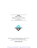
Page 1: ...l service in house repair center WE BUY USED EQUIPMENT Sell your excess underutilized and idle used equipment We also offer credit for buy backs and trade ins www artisantg com WeBuyEquipment REMOTE INSPECTION Remotely inspect equipment before purchasing with our interactive website at www instraview com LOOKING FOR MORE INFORMATION Visit us on the web at www artisantg com for more information on ...

Page 2: ...120 V1 6 AEROTECH Inc 101 Zeta Drive Pittsburgh PA 15238 2897 USA Phone 412 963 7470 Fax 412 963 7459 Product Service 412 967 6440 412 967 6870 Fax www aerotech com Artisan Technology Group Quality Instrumentation Guaranteed 888 88 SOURCE www artisantg com ...

Page 3: ...ed with new product information free downloadable software and special pricing on selected products The DR500 Drive Chassis Operation and Technical Manual Revision History Rev 1 1 January 31 1994 Rev 1 2 May 4 1995 Rev 1 3 November 6 1996 Rev 1 3a June 2 1997 Rev 1 4 March 12 1998 Rev 1 4a February 15 2000 Rev 1 5 December 12 2000 Rev 1 6 May 28 2002 Aerotech Inc 2002 Artisan Technology Group Qual...

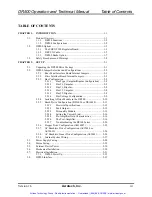
Page 4: ...olar 2 8 2 2 3 5 Bus 2 Bipolar 2 8 2 2 3 6 Bus Voltage Configuration 2 9 2 2 4 Installing A Drive Module in the DR500 2 10 2 2 5 Brush Drive Configuration DS16020 or DS16030 2 11 2 2 5 1 Electrical Specifications 2 12 2 2 5 2 Fault Output 2 12 2 2 5 3 Personality Module 2 13 2 2 5 4 Setting the Current Limit 2 16 2 2 5 5 Pre Amplifier Gain Characteristics 2 16 2 2 5 6 The Post Amplifier 2 16 2 2 5...

Page 5: ...4 Electrical Specifications 3 19 3 5 Environmental Specifications 3 20 3 6 Emergency Stop Sense Input 3 21 CHAPTER 4 SOFT START VOLTAGE SELECTOR BOARD 4 1 4 1 Soft Start Voltage Selector Overview 4 1 4 2 Soft Start Operation 4 2 4 3 Voltage Selector Function 4 3 4 4 Connector Pinouts 4 4 4 4 1 AC Input Power Connector J1 4 4 4 4 2 24 VDC Power Connector J2 4 4 4 4 3 Transformer Interface Connector...

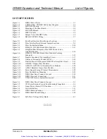
Page 6: ...on of Pre Amplifier Circuit 2 17 Figure 2 8 Outline of Personality Module RCN4 2 18 Figure 2 9 Detailed Electrical Diagram of DS160 Post Amplifier Circuit 2 19 Figure 2 10 AM16007 Stepper Drive Modules 2 22 Figure 2 11 AS32020 AS32030 AC Brushless Drive Modules 2 24 Figure 2 12 AS3005 Brushless Linear Drive Module 2 26 Figure 2 13 Power Supply Fusing 5V Adjust Potentiometer 2 28 Figure 2 14 Drive ...

Page 7: ...List of Figures DR500 Operation and Technical Manual vi Aerotech Inc Version 1 6 Artisan Technology Group Quality Instrumentation Guaranteed 888 88 SOURCE www artisantg com ...

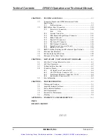
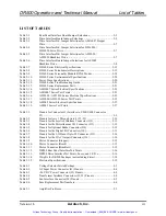
Page 8: ...eries Electrical Specifications 2 27 Table 2 19 AS3005 Series Test Points 2 27 Table 3 1 Pinouts for Connector J1 Interface to U500 U600 Connector P1 3 2 Table 3 2 Pinouts for Axis 1 Through Axis 4 J2 J5 3 10 Table 3 3 Pinouts for the Joystick Interface Connector J12 3 11 Table 3 4 Pinouts for the Miscellaneous I O Connector J13 3 12 Table 3 5 Pinouts for Optional Brake Connector J14 3 12 Table 3 ...

Page 9: ...iii Aerotech Inc Version 1 6 Table 5 2 Power Checks 5 3 Table 5 3 Fuse Replacement Part Numbers 5 4 Table 5 4 Preventative Maintenance 5 5 Table R 1 Revisions R 1 Artisan Technology Group Quality Instrumentation Guaranteed 888 88 SOURCE www artisantg com ...

Page 10: ...ectrical equipment for measurement control and laboratory use and complies with EMC directive 89 336 EEC and 73 23 EEC low voltage directive Pittsburgh PA David F Kincel_________________________ March 1998 Quality Assurance Manager Alex Weibel__________________________ Engineer Verifying Compliance General notes concerning the test setup This product was tested at Compliance Labs in Middlefield Oh...

Page 11: ...Regulatory Information DR500 Operation and Technical Manual x Aerotech Inc Version 1 6 Artisan Technology Group Quality Instrumentation Guaranteed 888 88 SOURCE www artisantg com ...

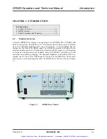
Page 12: ...ing that are inserted into the front of the DR500 panel The DR500 also provides bus power for the amplifier modules and acts as a breakout for all control and I O signals as well as mating to Aerotech s standard motor and feedback cables The DR500 is available in 19 inch rack mount and desktop packaging The individual amplifiers a maximum of four are inserted into the front of the DR500 panel The ...

Page 13: ...ction to the U500 U600 controller 1 1 2 DR500 Configurations The DR500 is easily configured to the users needs and can be set up for a wide range of applications It can be configured to House up to 4 DC servo AC brushless or microstepping amplifiers House from 1 to 4 amplifier modules House up to 2 transformers House optional brake control logic brake power and passive regeneration dissipation opt...

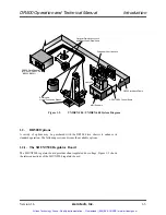
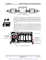
Page 14: ...1 2 1 The SHUNT500 Regulator Board The SHUNT500 regulator board provides shunt regulated bus voltage Figure 1 3 shows the interconnections of the SHUNT500 regulator board DR500 Drive Chassis or DR300 DR600 DR800 BB500 BB501 Rotary and Linear Positioning Stages Graphical User Interface OP500 Interface Cable Optional Digitizing Joystick and Electronic Handwheels MMI Software User s PC U500 U600 Cont...

Page 15: ... the side of the divider that supports the card rails Otherwise the board is mounted to the right side of the chassis to regulate the bus power supply connected to axis 4 Figure 1 4 Mounting of the Shunt Board DR500 DR 500 Mount Shunt Bus1 Resistor ECR00115 on rail 4 hole points from support panel using resistor mounting hardware EIH00456 SHUNT BUS1 Axis 1 2 Mount Shunt Bus1 Regulator EFN00169 to ...

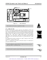
Page 16: ...the DR500 to provide Hall effect inputs and extra I O with an additional connection for an optional PB8 PB16 or PB24 I O board The second purpose is to allow more than four user inputs or outputs as in the case when the PB8 PB16 or PB24 I O board is used Figure 1 6 is an illustration of the DRC I O cable Refer to Figure 1 7 for illustrations of two versions of the DRC I O cable See the U600 Hardwa...

Page 17: ...ts and Hall Effect Inputs Output Wiring 8 Output Wiring 8 Input 8 and Output 8 Wiring Input 16 and Output 8 Wiring Input 16 and Output 8 Wiring Input 8 and Output 8 Wiring J10 TO DR300 Connect shield wire to pin 50 this end only Red line is 1 then cover with heatshrink 2 pls 15 Feet Approx 3 both ends AMP PN 3425 6050 Qty 2 To UNIDEX 500 P5 OR UNIDEX 600 P10 Shielded Ribbon Cable 3M PN 3659 50 Art...

Page 18: ...rive Interface Board and the Rear Panel Interface Board that are used to sense the switching of the motor leads of PWM amplifiers Additional modifications may also be included to meet particular brake standards Figure 1 8 BRAKE OPTION Wiring Brake output J14 is typically 24 volts Y Axis X Axis Z Axis Vertical Braking IMPORTANT P3 2 1 1 2 P4 P3 1 2 3 4 5 6 7 8 9 10 OUT OUT Power Supply Brake PS Bra...

Page 19: ...Deviation from this may result in damage to the equipment or the machinery To minimize the possibility of electrical shock and bodily injury when servicing the equipment ensure that all electrical power switches are in the off position and disconnect main power To minimize the possibility of electrical shock and bodily injury extreme care must be exercised when any electrical circuits are in use t...

Page 20: ...maged during unpacking Remove the packing list from the DR500 container Make sure that the items specified on the packing list are contained within the package Certain items required for use with your DR500 are not included within the DR500 shipping container These items may be found in the UNIDEX 500 600 shipping container The DR500 Drive Chassis One to four axis amplifier chassis with power supp...

Page 21: ...ard s jumpers Figure 2 1 Rear Panel Interface Board Jumper Locations J12 11 J100 J10 FROM CONTROLLER P5 1 J11 I O BUS 1 J3 AXIS 2 1 J4 AXIS 3 1 J2 AXIS 1 1 J5 AXIS 4 1 J13 MISC I O 1 J16 ICMD SIGNALS 1 J12 JOYSTICK 1 J14 BRAKE 1 J1 FROM CONTROLLER P1 DS5 I O BUS POWER DS1 ENCODER 1 POWER DS2 ENCODER 2 POWER DS3 ENCODER 3 POWER DS4 ENCODER 4 POWER 1 R30 R29 R28 R27 R26 C4 C3 C1 C2 100UF 001UF 10UF ...

Page 22: ...ve JP7 JP7 1 2 JP7 2 3 Axis 4 Remove JP8 JP8 1 2 JP8 2 3 Brake Output to Axis Connector No Brake Brake Present Axis 1 J2 Remove JP28A JP29A JP28A 1 2 JP29A 1 2 Axis 2 J3 Remove JP28B JP29B JP28B 3 4 JP29B 3 4 Axis 3 J4 Remove JP28C JP29C JP28C 5 6 JP29C 5 6 Axis 4 J5 Remove JP28D JP29D JP28D 7 8 JP29D 7 8 5 Volt Operation 24 Volt Operation E Stop Voltage Level Insert JP14 Remove JP14 Isolate Pins ...

Page 23: ...TP 14 TP 16 TP 17 27 37 47 17 28 TEST POINTS 29 39 JUMPERS JPxx JP26 JP36 JP46 JP16 JP41 JP42 JP45 JP43 M11 7407 1 2 BW40 F S 3 BW43 Q5 Q6 Q7 Q8 MMBT2222 8 Q1 Q2 Q3 Q4 JP35 JP33 M8 M9 M10 74AC14 74AC05 74AC05 1 2 BW30 F S 3 BW33 BW3 BW34 BW53 TR1 7 OHM F S TR2 7 OHM F S J9 30 32 4 6 J8 30 32 4 6 JP22 JP20 JP25 JP23 M5 M6 M7 74AC14 74AC05 74AC05 1 2 BW20 F S 3 BW23 BW2 BW24 BW52 J7 30 32 4 6 TEST P...

Page 24: ...8 Install JP18 1 2 Install JP18 2 3 Axis 2 Remove JP28 Install JP28 1 2 Install JP28 2 3 Axis 3 Remove JP38 Install JP38 1 2 Install JP38 2 3 Axis 4 Remove JP48 Install JP48 1 2 Install JP48 2 3 Amplifier Enable Active High Active Low Axis 1 Install JP19 1 2 Install JP19 2 3 Remove JP19 1 2 Axis 2 Install JP29 1 2 Install JP29 2 3 Remove JP29 1 2 Axis 3 Install JP39 1 2 Install JP39 2 3 Remove JP3...

Page 25: ...BW57 Add TR3 TR4 CL 11 ECR130 Bipolar X 30 Install BW8 EIK00226 QUICK CONN TAB BW56 BW57 Remove BW7 BW9 30 40 30 80 30 160 30 160LT 40 30 40 80 40 160 40 160LT 80 30 80 40 80 160 80 160LT 160 30 160 40 160 80 160 160LT 160LT 30 160LT 40 160LT 80 160LT 160 Bus Voltages Different Split 2 2 IN BW1 BW3 BW14 BW34 BW51 BW53 OUT BW2 BW24 BW52 Split 1 3 IN BW2 BW3 BW24 BW34 BW52 BW53 OUT BW1 BW14 BW51 Spl...

Page 26: ...6 IN BW45 46 IN PHASE D B BW10 OUT BW20 OUT BW30 OUT BW40 OUT DRIVE 5V JP12 OUT JP22 OUT JP32 OUT JP42 OUT MODE JP10 OUT JP20 OUT JP30 OUT JP40 OUT ICMDA JP11 OUT JP21 OUT JP31 OUT JP41 OUT AMP FAULT JP13 2 3 JP23 2 3 JP33 2 3 JP43 2 3 DRIVE KEY POS B POS B POS B POS B TACH JP15 IN JP25 IN JP35 IN JP45 IN PHASE A BW13 IN BW23 IN BW33 IN BW43 IN Table 2 5 Drive Interface Bd Jumper Selections for AS...

Page 27: ... power voltages are derived from isolation transformers autotransformers or offline depending on the line voltage bus voltage and other factors The bus supply information can be obtained from the DR500 system drawing provided with the DR500 2 2 3 1 Bus Type Unipolar Bipolar Configuration The DR500 Bus supplies are normally configured at that factory when the system is built These supplies should n...

Page 28: ...s supply 1 and BW7 Bus supply 2 Bus supply 1 contains capacitors C1 and C2 and bus supply 2 contains capacitors C3 and C4 These capacitors are 100 volt capacitors for bus voltages of 80 volts or less and 200 volt capacitors for bus voltages greater than 80 volts If Bus supply 1 has no transformer i e 160LT x insert F8 otherwise insert BW11 Likewise if Bus supply 2 i e x 160LT has no transformer in...

Page 29: ...otor drive modules the AS series There are two types of jumpers discussed in the following sections two pin headers and 16 gauge solid bus wire The two pin header jumpers are designated as JPx where the x corresponds to a specific axis e g JP23 is an axis 2 jumper JP43 is an axis 4 jumper JP13 is an axis 1 jumper etc All the non axis specific jumpers are outside the range of 10 through 49 The desi...

Page 30: ...ry ensure that all electrical power switches are in the off position and disconnect main power for 1 minute before inserting removing drive modules or changing jumper configurations To prevent another drive type from being inadvertently inserted into a slot configured for another type of drive module the mating drive connector on the motherboard should have a key Aerotech part number EAM857 otherw...

Page 31: ...et Volts Adjustable to Zero Power Amplifier Gain continuous output Amps Volt 1 2 Bandwidth kHz 1 PWM Switching Frequency kHz 20 Output Current Limit Amps max Adjustable Zero to Peak Shutdown Input Tristates Motor Output Minimum Load Inductance mH 2 Operating Temperature C 0 to 50 Storage Temperature C 30 to 85 Weight kg lb 0 5 1 Two control sections pre amplifier and post amplifier in dotted lines...

Page 32: ...s of adjusting the DC gain of the tach feedback signal present at J1 Pin 18 Turning this pot CW increases gain Balance Provides the means of canceling small DC offsets that may be present in the pre amplifier circuit Current Limit Provides a means of adjusting the clamp levels of the current command signal produced by the output of the pre amplifier Turning this pot CCW increases the clamp levels ...

Page 33: ...Stage Receiver A Receiver B Short Circuit Sensor J1 28 B Bus J1 26 30 Motor J1 J1 32 B Return Connections Pre Amplifier Details in Figures 2 6 and 2 7 Post Amplifier Details in Figure 2 9 Input Output Transfer Convention Open Loop A plus voltage on either input ortach with respect to signal common produces a net plus voltage on motor connection 26 with respect to motor connection 30 Patent No 4 55...

Page 34: ... 1 10K 1 TURN R13 10K R48 1 5K 5 0 OHM SELECT 12 7 SELECT 0 OHM 10 RCN4 E RCN4 G 4 SELECT 0 OHM 13 6 SELECT 0 OHM 11 RCN4 D RCN4 F 3 SELECT 0 OHM 14 RCN4 C 12V 8 7 NC 6 A3 2 3 4 5 1 1 10K 1 TURN 2 P3 CW 3 12V 12V R44 4 7K A A A 1N4148 1N4148 1N4148 D5 D6 D7 K K K A A A A 1N4148 1N4148 1N4148 ZM4736A D8 D9 D10 DZ9 K K K K K R45 DZ10 4 7K ZM4736A A 12V 10K 1 TURN 3 P1 1 CW 2 8 SELECT 0 OHM 9 RCN4 H ...

Page 35: ...ernal current command signal Icom is shown in Figure 2 7 The gain curves shown in Figure 2 7 are in relation to the values of RCN4 shown in Figure 2 6 2 2 5 6 The Post Amplifier A detailed circuit description of the post amplifier shown by dotted lines in Figure 2 5 is outlined in Figure 2 9 The circuitry shown in Figure 2 9 is for reference only and is not intended to be altered by the user Figur...

Page 36: ... 10 100 1000 10000 100000 Gain dB Transfer Function Icom Vcom Frequency Hz Tach Pot Full CCW Tach Pot Full CW Gain Pot Center Gain Pot Full CW 80 60 40 20 0 1 1 10 100 1000 10000 100000 Gain dB Transfer Function Icom Vfb Frequency Hz Note Transfer functions shown above are with respect to values of RCN4 shown in Figure 2 5 Artisan Technology Group Quality Instrumentation Guaranteed 888 88 SOURCE w...

Page 37: ...en 1uF 6 11 7 10 Open Open 8 9 The surface mount version of this module has a 0 ohm resistor in series with each component listed 8 7 6 5 4 3 2 1 9 10 11 12 13 14 15 16 16 Pin DIP Wafer snap on cover removed RCN4 1 16 Resistor Watt RCN4 2 15 Resistor Watt RCN4 3 14 Resistor Watt RCN4 4 13 Resistor Watt RCN4 5 12 Ceramic Capacitor 50V RCN4 6 11 Resistor Watt RCN4 7 10 Resistor Watt RCN4 8 9 Resisto...

Page 38: ... 001 20K 001 200K Icom 20K Ifb Op Amp Triangle Wave Generator 20K 20K 1M 50 µSec Triangle Wave Reference 0 8V out P P 8 µSec Dead Time typ 0 0 0 A B Delay Delay 12V 1 5K Comp Notes Typical Op Amp Gain 200 V mV Open Loop Values shown above are factory set Artisan Technology Group Quality Instrumentation Guaranteed 888 88 SOURCE www artisantg com ...

Page 39: ...heatsink not the enclosure Storage Temp C 85 max 30 min Shelf storage only not stand by use Humidity 10 90 Non condensing Table 2 11 Power Stage Specifications Unit Value Pin Comment Short Circuit Trip Amps min 40 J1 26 30 Requires power down reset Max may be as high as 60 amps Typical input output impedance Ohms max 3 J1 26 28 30 32 From bus connection 28 or 32 to motor connection 26 or 30 DC bus...

Page 40: ...ated to full speed when power was applied Personality module removed See Figure 2 6 Motor has high pitch oscillation sound when power is applied Tach and or Gain pot turned too high See Figure 2 6 Ripple current peak to peak in excess of 20 of continuous return of motor due to too high pre amplifier gains See Figure 2 6 Motor gets excessively hot when running at minimum load condition reference cu...

Page 41: ...e off position for 1 minute before inserting removing drive modules or changing jumper configurations To prevent another drive type from being inadvertently inserted into a slot configured for another type drive module the mating drive connector on the motherboard should have a key Aerotech part number EAM857 otherwise Schroff 21101 252 inserted into slot C Refer to Figure 2 3 Electrical specifica...

Page 42: ...fier Gain continuous output Amps Volt 75 PWM Switching Frequency kHz 20 Shutdown Input Tristates Motor Output Minimum Load Inductance mH 2 Operating Temperature C 0 to 50 Storage Temperature C 30 to 85 Weight kg lb 0 3 65 Table 2 15 AM16007 Series Test Points Test Point Signal TP3 Triangle Wave 20 kHz TP4 Common TP5 Sin I Command TP6 Sin I Feedback TP2 Cos I Command TP1 Cos I Feedback Artisan Tech...

Page 43: ... for 1 minute before inserting removing drive modules or changing jumper configurations To prevent another drive type from being inadvertently inserted into a slot configured for another type drive module the mating drive connector on the motherboard should have a key Aerotech part number EAM857 otherwise Schroff 21101 252 inserted into slot A Refer to Figure 2 3 Electrical specifications and test...

Page 44: ...witching Frequency kHz 20 Output Current Limit Amps max Adjustable Zero to Peak Shutdown Input Tristates Motor Output Minimum Load Inductance mH 2 Operating Temperature C 0 to 50 Storage Temperature C 30 to 85 Weight kg lb 0 5 1 320VDC but limited by internal bus power supply to 160VDC Table 2 17 AS32020 AS32030 Series Test Points Test Point Signal TP4 Common TP5 5V TP6 Phase A Current Command TP7...

Page 45: ...rations To prevent another drive type from being inadvertently inserted into a slot configured for another type drive module the mating drive connector on the motherboard should have a key Aerotech part number EAM857 otherwise Schroff 21101 252 inserted into both the A and E slot Refer to Figure 2 3 Electrical specifications and test points are listed in Table 2 18 and Table 2 19 respectively If t...

Page 46: ...st Point Signal TP5 Phase C Current Feedback TP8 Phase B Current Feedback TP10 Phase A Current Feedback TP12 Torque Command Phase A TP6 Phase C Current Command TP9 Phase B Current Command TP11 Phase A Current Command TP7 Torque Command Phase B DS1 L E D Drive Enable TP4 Common TP3 12V TP2 12V P2 Phase B Offset Adjust P3 Phase A Offset Adjust P4 Phase C Offset Adjust 2 2 9 Internal System Wiring Th...

Page 47: ...and disconnect main power for 1 minute before inserting removing drive modules or changing jumper configurations Aside from the two Bus power supplies the DR500 contains a power supply that provides 5 12 12 and 24 VDC This supply is located on the left side of the DR500 and is not user serviceable Several re settable fuses are located on the interface board for external 5V usage These fuses do not...

Page 48: ...n the off position and disconnect main power Turn off the DR500 power switch Loosen the two screws on the cover plate of the drive module securing it to the front of the chassis refer to Figure 2 14 Remove the drive module from the DR500 refer to Figure 2 14 Check for proper fuse size and type and replace the fuse on the drive module Figure 2 14 Drive Module Fuse Mounting WARNING DR 500 See Sectio...

Page 49: ... 412 963 7000 USA 412 963 7470 Sales FAX 412 963 7459 101 Zeta Drive World Headquarters Pittsburgh PA 15238 USA UK 0734 817274 FAX 0734 815022 Deutschland 0911 52031 FAX 0911 5215235 AXIS 4 AXIS 3 AXIS 2 JOYSTICK 1 ENCODER 3 POWER OK ENCODER 2 POWER OK ENCODER 1 POWER OK AXIS 1 1 AXIS 2 1 FROM CONTROLLER P5 1 I O BUS POWER OK I O BUS 1 AXIS 3 1 AXIS 4 1 MISC I O 1 BRAKE 1 FROM CONTROLLER P1 1 XIO ...

Page 50: ...e the optional DIOSR DRC cable that connects to P5 of the U500 or P10 of the U600 and to the rear of the DR500 to connector J10 labeled From UNIDEX 500 P5 U600 P10 This cable accommodates Hall effect feedback devices For applications that require resolver or inductosyn feedback connect these cables directly to the resolver option board within the personal computer When using the optional joystick ...

Page 51: ...ng AC power and provides protection for to the DR500 system in case of overloads This breaker is selected to meet the current requirements of the DR500 system and is normally either a 5 amp or 10 amp breaker The external 5 volt connections are fused by re settable fuses located on the interface board These fuses protect the system should a fault or overload condition occur with the optical encoder...

Page 52: ...able The purpose of this cable is to connect the brushless motor Hall effect signals via the I O bus to the U500 U600 controller board This requires an additional 50 conductor ribbon cable DIOSR DRC see Figure 2 17 connected from P5 on the UNIDEX 500 or P10 on the UNIDEX 600 to the connector on the rear of the DR500 chassis labeled From U500 P5 U600 P10 except for the U500PCI A system drawing is p...

Page 53: ...T 4J1 Axis 4 Mot Output J5 Axis 4 ENC LMT J11 I O Bus DC MSO 630C1380 EFO125 Or 630C1383 SMS O 630C1341 EFO120 Or 630C1382 Brushless Motor Cable BMC1 630C1544 Or 630C1529 Brushless Motor Feedback Cable BFC EFO140 Opto22 Board PB8 PB16 PB24 Optional HOME LIMIT OPTIONAL ALL AEROTECH CONTROLS ARE CONFIGURED TO ACCEPT A HOME LIMIT INPUT FOR GENERATING A COLD STARTING REFERENCE POINT THIS INPUT MAY COM...

Page 54: ...location of the connectors on the rear of the DR500 Chassis assembly Figure 3 1 DR500 Rear Panel Connector Layout ENCODER 4 POWER OK USA Service FAX 412 963 7000 USA 412 963 7470 Sales FAX 412 963 7459 101 Zeta Drive World Headquarters Pittsburgh PA 15238 USA UK 0734 817274 FAX 0734 815022 Deutschland 0911 52031 FAX 0911 5215235 AXIS 4 AXIS 3 AXIS 2 JOYSTICK 1 ENCODER 3 POWER OK ENCODER 2 POWER OK...

Page 55: ... Cosine Encoder Axis 3 76 Axis Fault 4 27 Marker Encoder Axis 3 77 Common 28 Marker Encoder Axis 3 78 Common 29 Hall Effect HA3 79 Current Command Axis 1 30 Hall Effect HC3 80 Current Command Axis 1 Phase 2 31 Sine Encoder Axis 4 81 Current Command Axis 2 32 Sine Encoder Axis 4 82 Current Command Axis 2 Phase 2 33 Cosine Encoder Axis 4 83 Current Command Axis 3 34 Cosine Encoder Axis 4 84 Current ...

Page 56: ... synchronize the switching of the power output circuits This is currently not used by any drive modules This pin may also be configured as common Pins 3 4 Encoder Power These 5 volt Encoder Power inputs are not normally used by the DR500 These connections are used to provide optional 5 volt power from the U500 U600 board Pins 51 77 78 87 These pins are common to the power supply The following pins...

Page 57: ...n 1 6 FORCER WIRES MOVE Clockwise FORCER MAGNET TRACK Figure 3 2 CW Motor Rotation Viewed from Mounting Flange End Figure 3 3 Linear Motor Forcer CW Direction COS COS N SIN SIN N MKR MKR N Artisan Technology Group Quality Instrumentation Guaranteed 888 88 SOURCE www artisantg com ...

Page 58: ...ndication from the motor that is used for homing the axis to an absolute reference position Pin 12 Marker N This is the active low marker output from a differential quadrature type square wave encoder Pin 52 HC1 This is axis 1 Hall Effect Sensor C output AXIS 2 PINOUTS INCLUDE Pin 13 HB2 This is axis 2 Hall Effect Sensor B output Pin 14 HA2 This is axis 2 Hall Effect Sensor A output Pins 15 to 20 ...

Page 59: ... stops all clockwise motion of the motor Pin 46 CCW Limit Axis 4 When activated this signal immediately stops all counter clockwise motion of the motor Pin 47 Home Limit Axis 1 This is the home limit switch output for axis 1 It is the same as the CW CCW limit outputs except that it is used only during the home cycle to find a reference point to begin looking for the once per revolution marker puls...

Page 60: ...00 600 manuals for additional information concerning the user inputs Pin 59 User Input 0 This is the least significant input bit Refer to the description given above Pin 60 User Input 1 Refer to the description preceding pin 59 Pin 61 User Input 2 Refer to the description preceding pin 59 Pin 62 User Input 3 Refer to the description preceding pin 59 The following four signals are the same user out...

Page 61: ... preceding pin 73 Pin 75 Axis Fault 3 Output Refer to the description preceding pin 73 Pin 76 Axis Fault 4 Output Refer to the description preceding pin 73 Each of the following four pairs of inputs are the analog current command signals for the drive modules The current commands are generated on the U500 U600 board by a serial D A converter with 16 bit resolution scaled to a range that includes 1...

Page 62: ...bove Pin 92 Joystick Button B Output Refer to the description preceding pin 91 Pin 93 Joystick Button C Interlock Refer to the description preceding pin 91 Pin 94 Brake Output This input signal disengages an optional normally on electromagnetic brake driven by an open collector buffer With the optional brake hardware present there is a 10k ohm pull up resistor to the 5 volt logic supply The follow...

Page 63: ...Description 1 Shield Chassis Frame 14 Cosine Input 2 Auxiliary Shutdown Input Remove JPx4 in DR500 to enable 15 Cosine N Input 3 5 Volts 16 Limit Switch Power 5V or 12V 4 Common 17 Sine Input 5 Hall Effect Sensor B Input 18 Sine N Input 6 Marker N Input 19 Tachometer Input 7 Marker Input 20 Common Limit 8 Tachometer Input 21 Common Encoder 9 Reserved for setup special option 22 Home Limit Input 10...

Page 64: ...Input 10 3 Joystick Potentiometer 1 Input 11 4 Common 12 5 13 Joystick Interlock common Input 6 Joystick Potentiometer 2 Input 14 7 Joystick Button B C Input 15 8 Figure 3 4 Joystick Interface 8 15 9 1 Joy X Joy Y Button A Button B Joy Interlock Common 5V Com 5V Com 100 Typ 2 plc s B A C Speed Select Buttons all N O Axis Pair Select Exit Slew Mode IN914 Button B Button C Button A Arrows below show...

Page 65: ...xis 2 19 5 Volts 7 Fault Axis 3 20 User Common 8 Fault Axis 4 21 User 12 Volts 500mA max 9 Brake Output 22 Common 10 Shutdown Axis 1 23 Reserved 11 Shutdown Axis 2 24 Analog Input 0 12 Shutdown Axis 3 25 Analog Input 1 13 Shutdown Axis 4 3 2 4 Brake Connector Table 3 5 shows the pinouts for the brake connector The mate to this connector is a Cinch DA 15P Aerotech ECK100 The optional fail safe brak...

Page 66: ... J10 Pin Description Pin Description 1 Input 15 Axis 4 Hall switch 25 Input 3 3 Input 14 Axis 4 Hall switch 27 Input 2 5 Input 13 Axis 4 Hall switch 29 Input 1 7 Input 12 Axis 3 Hall switch 31 Input 0 9 Input 11 Axis 3 Hall switch 33 Output 7 11 Input 10 Axis 3 Hall switch 35 Output 6 13 Input 9 Axis 2 Hall switch 37 Output 5 15 Input 8 Axis 2 Hall switch 39 Output 4 17 Input 7 Axis 2 Hall switch ...

Page 67: ...Output 14 6 Input 10 Axis 3 Hall switch 19 Output 5 Output 13 7 Input 9 Axis 2 Hall switch 20 Output 4 Output 12 8 Input 8 Axis 2 Hall switch 21 Output 3 9 Input 7 Axis 2 Hall switch 22 Output 2 10 Input 6 Axis 1 Hall switch 23 Output 1 11 Input 5 Axis 1 Hall switch 24 Output 0 12 Input 4 Axis 1 Hall switch 25 5 Volts 13 Input 3 User Reset Input 26 50 Common Pins 17 through 20 are Outputs 12 throu...

Page 68: ...Motor Connector Stepper Pin Description 1 motor frame 8 motor shield 2 phase A 7 phase A 4 phase B 3 phase B For a DC Brush motor connector the following pins apply Table 3 10 Motor Connector Brush Pin Description 1 motor frame 8 motor shield 5 7 motor 4 6 motor For an AC Brushless motor connector the following pins apply Table 3 11 Motor Connector Brushless Pin Description 1 motor frame 8 motor s...

Page 69: ...able 4 Pad 4 J2 1 DS1 L E D J3 2 DS2 L E D J4 3 DS3 L E D Encoder Power J5 4 DS4 L E D 1 TP12 2 TP22 3 TP32 Optional Encoder Setup Sig 4 TP42 Internal 5V Power TP2 Table 3 13 DR500 Drive InterfaceTest Points Fuses and L E D s Signal Axis Test Point or Indicator Brake Disabled DS1 L E D Brake Fuse F9 Bus 1 Fuse F8 Bus 2 Fuse F10 ESTOP TP5 1 TP14 2 TP15 3 TP16 Drive Enable 4 TP17 J2 Pin 23 1 TP7 J3 ...

Page 70: ...y wider front panel that includes handles and mounting flanges see Figure 3 6 The package depth does not allow for the required space at the back of the chassis to allow for motor and user cable connections Figure 3 5 DR500 Desktop Package 9 25 OFF ON 431 8 17 0 203 2 8 0 203 2 8 0 235 0 222 3 8 75 12 7 0 50 Allow 6 152 4mm for wire bends and connectors DR 500 AEROTECH AEROTECH AEROTECH AEROTECH A...

Page 71: ...0 and 160V Bus 2 17lbs 7 7kg 25lbs 11 3kg 25lbs 11 3kg 115VAC 4 17lbs 7 7kg 33lbs 14 9kg 25lbs 11 3kg 2 25lbs 11 3kg 25lbs 11 3kg 25lbs 11 3kg 100 208 and 230VAC 4 33lbs 14 9kg 33lbs 14 9kg 33lbs 14 9kg 431 8 17 0 203 2 8 0 203 2 8 0 222 3 8 75 Allow 6 152 4mm for wire bends and connectors DR 500 AEROTECH AEROTECH AEROTECH AEROTECH AEROTECH ON OFF DIMENSIONS Millimeters Inches 482 6 19 0 Handle Ar...

Page 72: ...e Example 115V 50 60Hz 5A Hazardous voltage may be present Table 3 15 Electrical Specifications VAC IN RMS of Axis Max AC Line Input Bus Voltage Max Watts Out 2 5A 40 60 80 350 115VAC 2 10A 160 1000 10 4 10A 40 60 80 160 2000 230VAC 2 5A 40 60 80 160 350 10 4 5A 40 60 80 160 700 100VAC 2 5A 40 60 80 160 350 10 4 10A 40 60 80 160 700 208VAC 2 5A 40 60 80 160 350 10 4 5A 40 60 80 160 700 Line Freque...

Page 73: ...F Storage 20 70 C 4 158 F Humidity Maximum relative humidity is 80 for temperatures up to 31 C Decreasing linearly to 50 relative humidity at 40 C Non condensing Altitude Up to 2 000 m Pollution Pollution degree 2 normally only non conductive pollution Use Indoor use only Artisan Technology Group Quality Instrumentation Guaranteed 888 88 SOURCE www artisantg com ...

Page 74: ...ergency stop sense input See your controller s hardware manual for more information The U500 and U600 require a parameter change before it will recognize the ESTOP circuit Refer to the UNIDEX 500 Technical and Operation Manual or the UNIDEX 600 User s Guide for more details Artisan Technology Group Quality Instrumentation Guaranteed 888 88 SOURCE www artisantg com ...

Page 75: ...Technical Details DR500 Operation and Technical Manual 3 22 Aerotech Inc Version 1 6 Artisan Technology Group Quality Instrumentation Guaranteed 888 88 SOURCE www artisantg com ...

Page 76: ...o limit AC inrush current during turn on and selection of the AC line voltage The Soft Start Voltage Select Board is shown below Figure 4 1 Soft Start Voltage Select Board S2 4ASB F1 S1 3ASB F2 4ASB F3 S3 S4 3ASB F4 S1 S2 S3 S4 100VAC UP UP DN DN 115VAC UP UP UP UP 200VAC DN DN DN DN 230VAC DN DN UP UP SWITCH SETTINGS UP DN UP DN UP DN UP DN WARNING S1 S2 S3 AND S4 MUST BE SET FOR THE APPLIED AC P...

Page 77: ...g initial power up or when AC power interruptions last longer than 3 seconds Short Power interruptions less than about 3 seconds will not initiate a soft start activation This prevents the possibility of soft start induced nuisance trips during normal operation The Soft Start circuit requires 24 VDC for proper operation provided internally Damage to the Soft Start circuit may result if 24 VDC is n...

Page 78: ...itional information Example For 230VAC Operation Set S1 to DN position S2 to UP position S3 to DN position and S4 to UP position Table 4 1 Voltage Selector Switch Settings AC Volts S1 S2 S3 S4 100 VAC UP DN UP DN 115 VAC UP UP UP UP 200 VAC DN DN DN DN 230 VAC DN UP DN UP NOTE UP and DN refer to positions of S1 S4 shown in Figure 4 1 The Voltage Selector can only be used with transformers designed...

Page 79: ...ription Pin Description 1 COMMON 3 24 VDC 2 COMMON 4 24 VDC 4 4 3 Transformer Interface Connectors J3 J5 The pinouts for the Transformer Interface connectors are listed in Table 4 4 Table 4 4 Transformer Interface Connectors J3 J5 Pinouts Pin Description Pin Description 1 Transformer Thermal Switch WHT WIRE 5 Transformer 100VAC Lead GRN WIRE 2 Transformer 0VAC Lead BLU WIRE 6 Transformer 115VAC Le...

Page 80: ...r the Fan Interface connector are listed in Table 4 5 Table 4 5 Fan Interface Connector J4 Pinouts Pin Description 1 Fan AC HI 115VAC 2 FAN AC LO The Fan Interface Connector is for AC fans 115 VAC typical only Do Not Use With DC Fans Artisan Technology Group Quality Instrumentation Guaranteed 888 88 SOURCE www artisantg com ...

Page 81: ...uses F1 and F2 are used to protect the transformer connected to J3 Fuses F3 and F4 are used to protect the transformer connected to J5 Fuses are shown in Figure 4 1 Table 4 6 lists the Part s for these fuses Table 4 6 Fuse Replacement Part Numbers FUSE Manufacturer P N Aerotech P N 3 amp 3AG PN BK MDA 3 EIF103 4 amp 3AG PN BK MDA 4 EIF104 Disconnect Mains power before opening chassis Fuses must no...

Page 82: ...wing cautions and dangers when troubleshooting the DR500 There are no user serviceable parts The cord is the disconnect device when servicing Hazardous voltages may be present at power inlet and motor connectors Voltages up to 24 Volts may be present at I O and Brake connectors Motors must be mechanically secured before applying power Motor temperatures may exceed 50 C Danger risk of electric shoc...

Page 83: ... Verify Parameters Check Encoder and Hall feedback Check Amp and Bus fuses Motor oscillates or squeals when in position Check tuning parameters and gains Motor traps out Check parameters Check Encoder and Hall feedback phasing Motor load too high or mechanically locked Programmed speed too fast Motor unstable Check parameters Check Encoder and Hall feedback Motor runs away Check parameters Check E...

Page 84: ... Panel Interface Bd P5 is 5V P6 is common Check for 5 Volt short disconnect all cables to DR500 Check that the L E D s on the Rear Panel Interface Bd Are ON if an L E D is OFF this indicates that the associated connector may have a 5V short Note Latter versions use resettable fuse for 5V supply Reset by turning off power for 30 seconds Axis will not enable and or no motor torque Check 5 Volt suppl...

Page 85: ...use Littlefuse 235002 EIF195 1 amp 5x20mm fuse Littlefuse 218001 EIF189 5 amp CB1 ETA 3120 F321 P7T1 R14LB4 EAW254 10 amp CB1 ETA 3120 F321 P7T1 W19LB4 EAW260 Bus fuses are usually located in the left compartment transformer power supply area of the DR500 The system drawing and amplifier documentation contains information regarding the fuses on the power amps 10 12 and 15 amp fuses are not user re...

Page 86: ...ernal inspection is not required Parts should be repaired as required If internal damage is suspected these parts should be checked and repairs made if necessary Inspect cooling vents Remove any accumulated material from vents Check for fluids or electrically conductive material exposure Any fluids or electrically conductive material must not be permitted to enter the DR500 and should be removed i...

Page 87: ...d because internal contamination may result in electrical shorts and or corrosion The electrical power must be disconnected from the DR500 while cleaning Do not allow cleaning substance to enter DR500 or onto any of the connectors Cleaning labels on the rear panel should be avoided to prevent erasing of label information Artisan Technology Group Quality Instrumentation Guaranteed 888 88 SOURCE www...

Page 88: ...ded for all laser power supplies plasma tubes and laser systems subject to electrical or physical abuse tampering such as opening the housing or removal of the serial tag or improper operation as determined by Aerotech This warranty is also voided for failure to comply with Aerotech s return procedures Claims for shipment damage evident or concealed must be filed with the carrier by the buyer Aero...

Page 89: ...d service representative in a reasonable amount of time provided that the customer issues a valid purchase order to Aerotech covering all transportation and subsistence costs For warranty field repairs the customer will not be charged for the cost of labor and material If service is rendered at times other than normal work periods then special service rates apply If during the on site repair it is...

Page 90: ...2 10 Brake Connector Pinouts 3 12 Brake Mating Connector 3 12 Brake Output 3 9 breakout 1 1 Brush Drive Configuration 2 11 Brush Motor Drive Modules 2 10 Brushless Motor 2 33 Bus Power Supply Fuse Location 2 28 Bus Voltage 1 3 2 8 Bus Voltage Chart 3 19 Bus Voltage Configuration 2 8 Button C Joystick Input 3 9 C Cable Connections 2 31 3 17 Cables Connections 2 31 DIOSR DRC 2 33 Motor 2 31 OP500 2 ...

Page 91: ... O Cable 1 5 Drive Modules 2 10 AM Series 2 10 AS Series AC Brushless Motor 2 10 Brush Motor 2 10 DS Series Stepper Motor 2 10 Drive Power 1 1 DS Series Stepper Motor Drive Modules 2 10 DS16020 DS16030 Electrical specifications 2 12 2 23 2 25 2 27 Environmental specifications 2 20 Fault output 2 12 Personality module 2 13 Post amplifier specifications 2 16 2 19 Power stage specifications 2 20 Pre ...

Page 92: ... 3 3 M Maintaining Position 1 7 Marker Pinout 3 5 Marker Pulse 3 6 Mating Connectors Brake 3 12 From U500 P5 3 13 From U500 P5 Connector 3 13 I O or Opto 22 Bus 3 14 Miscellaneous I O 3 12 Motor Power 3 15 MFO Analog Input 3 9 Miscellaneous I O Connector 3 12 Pinouts 3 12 Miscellaneous I O Mating Connector 3 12 Mode Control Axis 2 Output 3 7 Mode Control Axis 3 Output 3 7 Mode Control Axis 4 Outpu...

Page 93: ...entiometer Description 2 13 Power Output Circuits 3 3 Synchronizing 3 3 Power problems 5 3 Power Supply 2 28 Bipolar 2 8 Unipolar 2 8 Power Switch 2 29 Power Up 2 32 Power Drive 1 1 Pre amplifier Gain characteristics 2 16 2 17 Preventative Maintenance 5 5 Procedures Cable Connection 2 31 Product Overview 1 1 Providing Power to Encoder 3 3 PWM Current Regulators 3 3 R Rack Mount Package 3 17 3 18 R...

Page 94: ... Pinout 3 7 V VAC IN Chart 3 19 Velocity Feedback 3 5 Verification Fuses 2 29 Voltage Selector Board Function 4 3 User Settable Switches S1 S4 4 3 Warnings 4 3 W Warranty Information A 1 Warranty Policy A 1 Weights Desktop Package 3 18 Panel Mount Package 3 18 Rack Mount Package 3 18 Wiring Internal System 2 27 Artisan Technology Group Quality Instrumentation Guaranteed 888 88 SOURCE www artisantg...

Page 95: ...Index DR500 Operation and Technical Manual vi Aerotech Inc Version 1 6 Artisan Technology Group Quality Instrumentation Guaranteed 888 88 SOURCE www artisantg com ...

Page 96: ...chapter will be listed with extensive changes in the corresponding General Information cell Table R 1 Revisions Revision Section s Affected General Information 2 2 2 In Table 2 2 part number ECR130 now refers to CL 11 not CL 10 as previously indicated 2 2 6 AM16007 Output Fuse F1 changes from 3 ASB to 10 ASB Chapter 4 New Chapter 4 Soft Start Voltage Selector Board 1 6 Chapter 5 Chapter 5 Troubles...

Page 97: ...Revision History DR300 Operation and Technical Manual R 2 Aerotech Inc Version 1 6 Artisan Technology Group Quality Instrumentation Guaranteed 888 88 SOURCE www artisantg com ...

Page 98: ...__________________________________________________________________ _____________________________________________________________________ _____________________________________________________________________ _____________________________________________________________________ _____________________________________________________________________ Your name ________________ Your title _______________...

Page 99: ...Artisan Technology Group Quality Instrumentation Guaranteed 888 88 SOURCE www artisantg com ...

Page 100: ...l service in house repair center WE BUY USED EQUIPMENT Sell your excess underutilized and idle used equipment We also offer credit for buy backs and trade ins www artisantg com WeBuyEquipment REMOTE INSPECTION Remotely inspect equipment before purchasing with our interactive website at www instraview com LOOKING FOR MORE INFORMATION Visit us on the web at www artisantg com for more information on ...

Reviews: