


DR500 Operation and Technical Manual
Technical Details
Version 1.6
Aerotech, Inc.
3-13
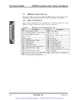
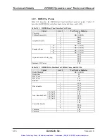
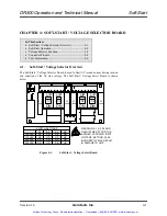
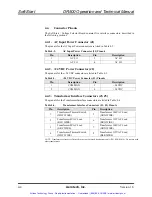
3.2.5. Digital I/O Connector
Table 3-6 shows the pinouts for the digital I/O or "From U500 P-5/U600 P10" connector.
The mate to this connector is a 3M #3425-6050 (Aerotech # ECK332).
This connector is normally used to connect to U500-P5 or U600-P10. This is
required if Hall effect sensors (brushless only) are used as shown in section 1.2.2. It
is not required for the U500PCI.
When looking at this connector, note that all even numbered pins, 2 through 50 are
common.
Table 3-6.
Pinouts for the Digital I/O Connector (J10)
Pin #
Description
Pin #
Description
1
Input 15/Axis 4 Hall switch
25
Input 3
3
Input 14/Axis 4 Hall switch
27
Input 2
5
Input 13/Axis 4 Hall switch
29
Input 1
7
Input 12/Axis 3 Hall switch
31
Input 0
9
Input 11/Axis 3 Hall switch
33
Output 7
11
Input 10/Axis 3 Hall switch
35
Output 6
13
Input 9/Axis 2 Hall switch
37
Output 5
15
Input 8/Axis 2 Hall switch
39
Output 4
17
Input 7/Axis 2 Hall switch
41
Output 3
19
Input 6/Axis 1 Hall switch
43
Output 2
21
Input 5/Axis 1 Hall switch
45
Output 1
23
Input 4/Axis 1 Hall switch
47
Output 0
24
49
The outputs are open collector devices and should only be exposed to +5 volt logic levels.
All outputs are tri-stated (high impedance) on reset.
1
50
49
2
Artisan Technology Group - Quality Instrumentation ... Guaranteed | (888) 88-SOURCE | www.artisantg.com