InteliDrive DCU Industrial 3.4.0 Global Guide
308
5. IS-BIN16/8
9
5
6. IS-BIN16/8
11
6
7. IS-BIN16/8
16
7
Table 8.1 Table of recommended CAN1 address setting
SW version check
Let suppose IS-AIN8 of SW version 1.4. Shortly press address button. Following sequence appears on the
display: number “1”, one second pause, number “4”, two second pause, number “1”, one second pause, number
“4”, two second pause and finally IS-AIN8 actual address.
Error message (e.g. SD BOUT2) appears on Controller screen when Binary input or output Address x is
configured but corresponding unit is not recognized (no message is received from CAN bus). Check IS
configuration and corresponding external IS-AIN, IS-BIN unit address setting.
LED indication
Tx
Rx
Dark
Blink
Light
Dark
Blink
Light
Any data are
transmitted on the
CAN1 line
Data are transmitted
on the CAN1 line
Any data are
received on the
CAN1 line
Data are received
on the CAN1 line
Table 8.2 Tx / Rx LED status
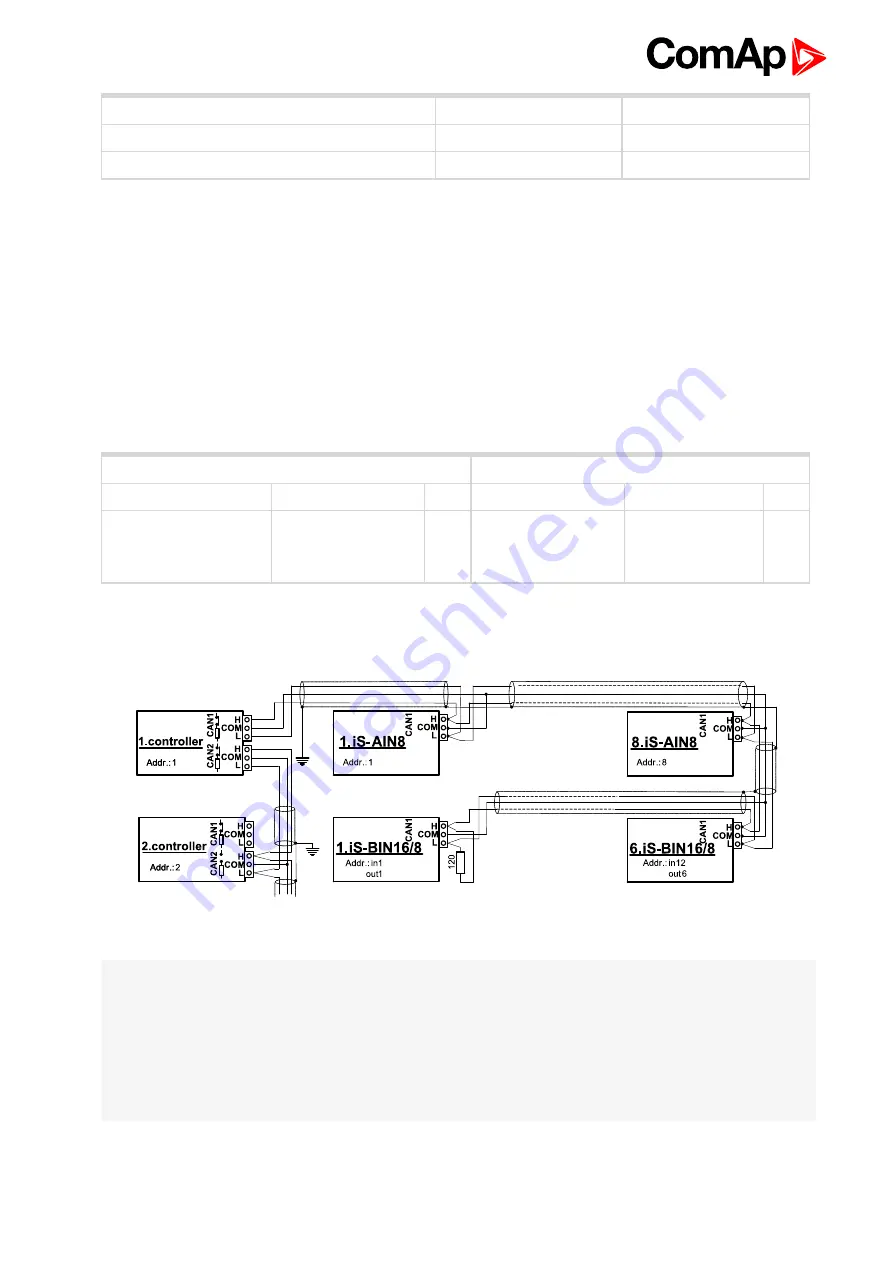
Wiring
Image 8.5 CAN bus line has to be terminated by 120 ohm resistors on the both ends.
Note:
CAN bus line has to be terminated by 120 ohm resistors on the both ends.
For longer distances is recommended to connect CAN COM terminals between all controllers and cable
shielding to the
ground in one point!
Recommended CAN bus data cables see in Chapter Technical data.
External units can be connected on the CAN bus line in any order, but line arrangement (no tails no star) is
necessary-
Recommended CAN bus data cables see in Chapter Technical data.
Summary of Contents for InteliDrive DCU Industrial
Page 5: ...InteliDrive DCU Industrial 3 4 0 Global Guide 5 8 2 13 Theory of binary inputs and outputs 347...
Page 29: ...InteliDrive DCU Industrial 3 4 0 Global Guide 29...
Page 97: ...InteliDrive DCU Industrial 3 4 0 Global Guide 97 8 Appendix 6 back to Table of contents...
Page 246: ...InteliDrive DCU Industrial 3 4 0 Global Guide 246 Analog inputs from J1939 configuration...
Page 263: ...InteliDrive DCU Industrial 3 4 0 Global Guide 263 6 back to List of setpoints...


