


Connecting the Input/Output Signals
33
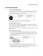
Connecting the Audio Outputs
Connectors for the Digital Audio Output
The configuration of the D9854/D9854-I receiver outputs two stereo channels. The
receiver also supports encoding of audio embedded in the HD-SDI video signal.
The following drawing shows the audio connector.
Connector
Interface type
Connector type
AES-292M
BNC female
Note:
The digital audio output is always 75-ohm single-ended.
Connecting the Digital Audio Outputs
Connect digital audio output broadcast equipment to the AES-3id connectors. The
two stereo channels are useful for Dolby Digital 5.1 passthrough applications. Use a
high-quality, double-shielded RJ6 coaxial cable.
Hint:
For digital audio connections, use a balanced cable designed for 110 -ohm AES-
EBU digital audio.
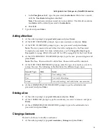
Connecting the Balanced Audio Output
1
Connect the AUDIO 1 and AUDIO 2 balanced audio outputs to monitoring
equipment. Use a multi-conductor, pluggable cable from the receiver's AUDIO 1
and AUDIO 2 (Left and Right) terminals to your equipment, as shown in the
following illustration.
Connector
Connector type
Terminal Block
2
Feed the stripped ends of the positive, negative and ground wires into the
appropriate terminals as labeled, and then screw the terminal screws (located on
the top of the terminal block) finger tight to each wire.
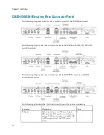
Summary of Contents for D9854
Page 21: ...Declaration of Conformity 410 Index 411 ...
Page 22: ......
Page 24: ......
Page 28: ...Chapter 1 Introduction 4 SCTE 104 pass through support on SDI output NIT Retune Recovery ...
Page 36: ......
Page 48: ......
Page 66: ......
Page 180: ......
Page 328: ......
Page 392: ......
Page 394: ......
Page 412: ......
Page 434: ...Appendix C Compliance 410 Declarationof Conformity ...
Page 439: ......