


Chapter 2 Quick Setup - Read Me First!
14
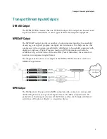
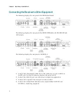
Connecting the Receiver to Other Equipment
The following displays the rear panel of the D9854 Base Model:
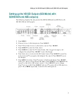
The following displays the rear panel of the D9854 SDI Model, with SD/HD-SDI and
AES outputs:
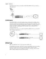
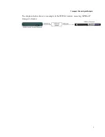
The following displays the rear panel of the D9854-I:
1
Connect the L-Band signal to RF1. 13V or 18V LNB power is only available on
the RF1 port. The factory default setting for LNB power is OFF.
2
Connect the ASI OUT port to an ASI device for digital tier applications.
3
Connect the Composite Video Output to a video monitor.
4
Connect the terminal block balanced audio outputs labeled AUDIO 1 and
AUDIO 2 to monitoring equipment.
Summary of Contents for D9854
Page 21: ...Declaration of Conformity 410 Index 411 ...
Page 22: ......
Page 24: ......
Page 28: ...Chapter 1 Introduction 4 SCTE 104 pass through support on SDI output NIT Retune Recovery ...
Page 36: ......
Page 48: ......
Page 66: ......
Page 180: ......
Page 328: ......
Page 392: ......
Page 394: ......
Page 412: ......
Page 434: ...Appendix C Compliance 410 Declarationof Conformity ...
Page 439: ......