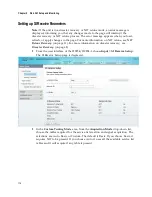
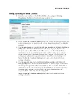

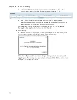


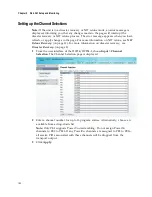
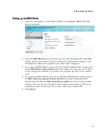

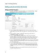

Setting up Input Information
191
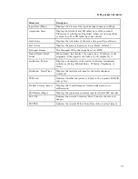
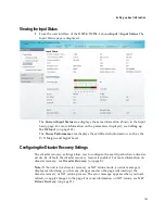
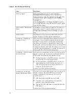
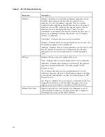
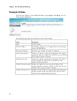
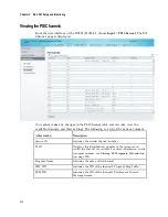
The
Signal Lock Timer
,
Signal Loss Timer
, and
Verification Timer
fields display
the signal lock, signal loss, and verification periods set on the Disaster Recovery
Setup page if the
Configured By
field is set to
User
. If the
Configured By
field is set
to
Uplink
, the disaster recovery profile settings from the PNC uplink are displayed.
But if the unit is not connected to the uplink, the default values of the unit are
displayed. For more information, contact your PNC uplink administrator.
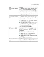
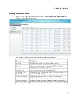
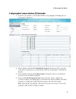
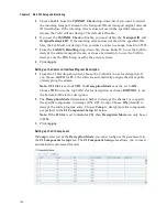
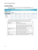
The
Backup Transport
area displays the tuning parameters of the current origin and
backup transports configured. For example, if only Backup 1 and Backup 3 are
configured, the table will display the tuning parameters for Origin, Backup 1, and
Backup 3. The Configured By row indicates that the backup transport is configured
by a user.
The
Search Path
area displays the channel numbers assigned to the Origin and
Backup transports for PE1 to PE16.
Summary of Contents for D9854
Page 21: ...Declaration of Conformity 410 Index 411 ...
Page 22: ......
Page 24: ......
Page 28: ...Chapter 1 Introduction 4 SCTE 104 pass through support on SDI output NIT Retune Recovery ...
Page 36: ......
Page 48: ......
Page 66: ......
Page 180: ......
Page 328: ......
Page 392: ......
Page 394: ......
Page 412: ......
Page 434: ...Appendix C Compliance 410 Declarationof Conformity ...
Page 439: ......