


Chapter 5 Web GUI Setup and Monitoring
250
4
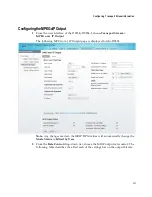
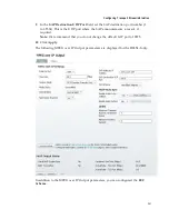
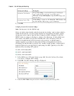
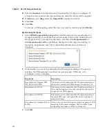
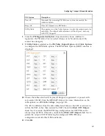
The generation of the FEC packets is based on the use of a matrix. The matrix
size is defined by the Length (L) and Depth (D) parameters. In the
FEC Columns
(L)
field, set the spacing between non-consecutive packets used to calculate the
FEC packet (1 to 20).
If the
FEC Mode
is set to
2D
, set the depth of the matrix in the
FEC Rows (D)
field (4 to 20).
Note:
For additional restrictions on L and D values (depending on the
FEC
Scheme
and
FEC Mode
), refer to Pro-MPEG FEC COP#3 and SMPTE-2022.
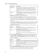
5
In the
FEC Columns UDP Port
field, enter the UDP port number for the FEC
Columns stream (2 to 65534, even number only).
Note:
We recommend that you set the
FEC Columns UDP Port
number to TS
UDP port + 2.
If the
FEC Mode
is set to
2D
, enter the destination UDP port number for the FEC
Rows stream in the
FEC Rows UDP Port
field (2 to 65534, even number only).
Note:
We recommend that you set the
FEC Rows UDP Port
number to TS UDP
port +4.
6
Click
OK
.
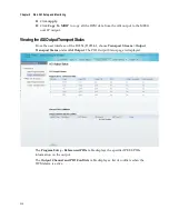
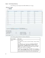
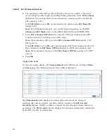
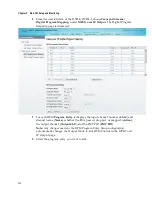
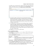
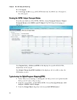
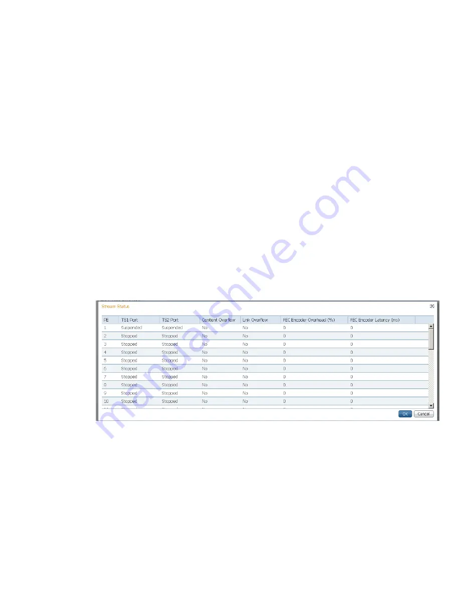
View ing Stream Details
To view the stream details, click
Stream Details
in the MPEG over IP Output
Main
or
Stream
page. The following Stream Status table is displayed.
The
Stream Status
table displays the status of the streams for the data port,
including the content overflow and link overflow statuses. The
FEC Encoder
Overhead
displays the FEC overhead, compared to the transport stream bit rate, in
percentage. The
FEC Latency
column displays the transport stream delay introduced
by the FEC encoder, in milliseconds.
Summary of Contents for D9854
Page 21: ...Declaration of Conformity 410 Index 411 ...
Page 22: ......
Page 24: ......
Page 28: ...Chapter 1 Introduction 4 SCTE 104 pass through support on SDI output NIT Retune Recovery ...
Page 36: ......
Page 48: ......
Page 66: ......
Page 180: ......
Page 328: ......
Page 392: ......
Page 394: ......
Page 412: ......
Page 434: ...Appendix C Compliance 410 Declarationof Conformity ...
Page 439: ......