


Chapter 5 Web GUI Setup and Monitoring
218
7
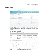
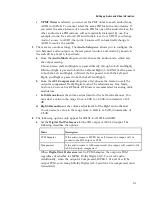
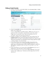
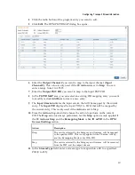
From the
Relay Mode
drop-down list, choose the relay mode that can be
programmed to respond to an Alarm state, Warning statue, or the state of one of
the eight cue trigger pins. The response is generated at the Cue Tone/Relay
output on the rear panel of the receiver. The following table shows what the
possible field settings are and their relationship to the receiver output:
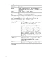
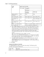
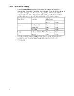
Relay Mode
Condition
Relay Contact
NC - C
C-NO
Alarm
Unit Power Off
Open
Close
Alarm State
Open
Close
No Alarm
Close
Open
Trigger
Active (selected in PNC) Close
Open
Inactive
Open
Close
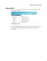
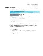
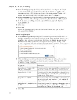
8
If the
Relay Mode
is set to
Trigger
, choose the cue trigger bit/pin that will
activate the relay from the
Relay Trigger Bit
drop-down list (1 to 8).
9
Click
Apply
.
Summary of Contents for D9854
Page 21: ...Declaration of Conformity 410 Index 411 ...
Page 22: ......
Page 24: ......
Page 28: ...Chapter 1 Introduction 4 SCTE 104 pass through support on SDI output NIT Retune Recovery ...
Page 36: ......
Page 48: ......
Page 66: ......
Page 180: ......
Page 328: ......
Page 392: ......
Page 394: ......
Page 412: ......
Page 434: ...Appendix C Compliance 410 Declarationof Conformity ...
Page 439: ......