


Chapter 4 Front Panel Operation
132
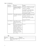
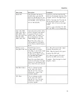
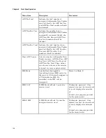
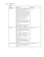
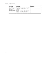
Setting
Mode Options
Description
Default
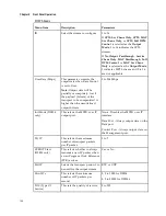
DRT
Pass, Drop
Disaster Recovery Table
Pass
CDT
Pass, Drop
Code Download Table
Pass
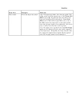
Note:
The CDT is different from the other tables listed because the CDT is referred to within
the PMT, rather than outside the PMT. Select
Pass
to permit the output of CDTs following
the configured DPM PID map configuration and all other DPM constraints. If a DPM PID
map has not been configured for the CDT PID and the PE Act is set to Map, the CDT will still
not output. Select
Drop
to override the DPM PID map configuration for CDT PIDs and to
always drop all CDTs.
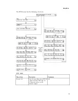
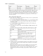
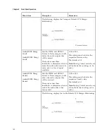
Setting Up Digital Program Mapping (DPM)
1
Verify that you are receiving a valid signal and that you have set up the channels
that you want to pass, drop or map.
2
Go to the
Setup
:
Outputs
,
TS Out
:
DPM
:
Global
menu and select
Resync All
for
the selected ASI output. This copies the input services PIDs to the remapped
output service PIDs.
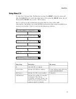
3
Go to
Setup
:
Outputs
:
TS Out
:
DPM
:
ASI
, and select the PE containing the
channel you want to configure.
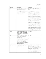
4
Set the
Act
for the selected PMT to either
Pass
,
Drop
, or
Map
depending on the
action desired.
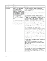
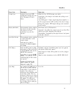
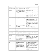
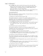
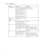
A program can be set to one of three output modes, either Drop, Pass or Map.
LCD Setting
Description
Drop
Removes the service and its associated PMT reference
from the transport output.
Pass
Permits the source content and PMT reference to
appear in the transport output with the same
references.
Map
Provides the flexibility to define all the outgoing PID
numbers for the PE, including those not currently on
transmission.
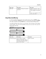
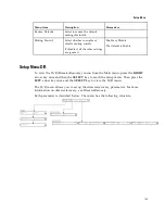
5
Use the
RIGHT
arrow key to move to the right and select PID to display the
detailed menu level.
6
Configure the input to output channel mapping. Video and PCR can be output
on the same PID or different PIDs. If output on the same PID, they will appear
identical to the input.
Note:
If the parameters cannot be saved, the problem may be that the incorrect
Map Mode has been selected. Ensure that Svc ID & PID is selected when
remapping PIDs, otherwise a message such as “Bad configuration data” will be
displayed and you will need to change the parameters to obtain the correct
output.
Summary of Contents for D9854
Page 21: ...Declaration of Conformity 410 Index 411 ...
Page 22: ......
Page 24: ......
Page 28: ...Chapter 1 Introduction 4 SCTE 104 pass through support on SDI output NIT Retune Recovery ...
Page 36: ......
Page 48: ......
Page 66: ......
Page 180: ......
Page 328: ......
Page 392: ......
Page 394: ......
Page 412: ......
Page 434: ...Appendix C Compliance 410 Declarationof Conformity ...
Page 439: ......