11. Expert operation
The effect of external Alpha and Beta Planes can be expressed as follows:
Projected image = Alpha Plane * Source image + Beta Plane
External and Internal Alpha and Beta Planes can be enabled simultaneously.
11.2.2 Soft Edge area shape
Description
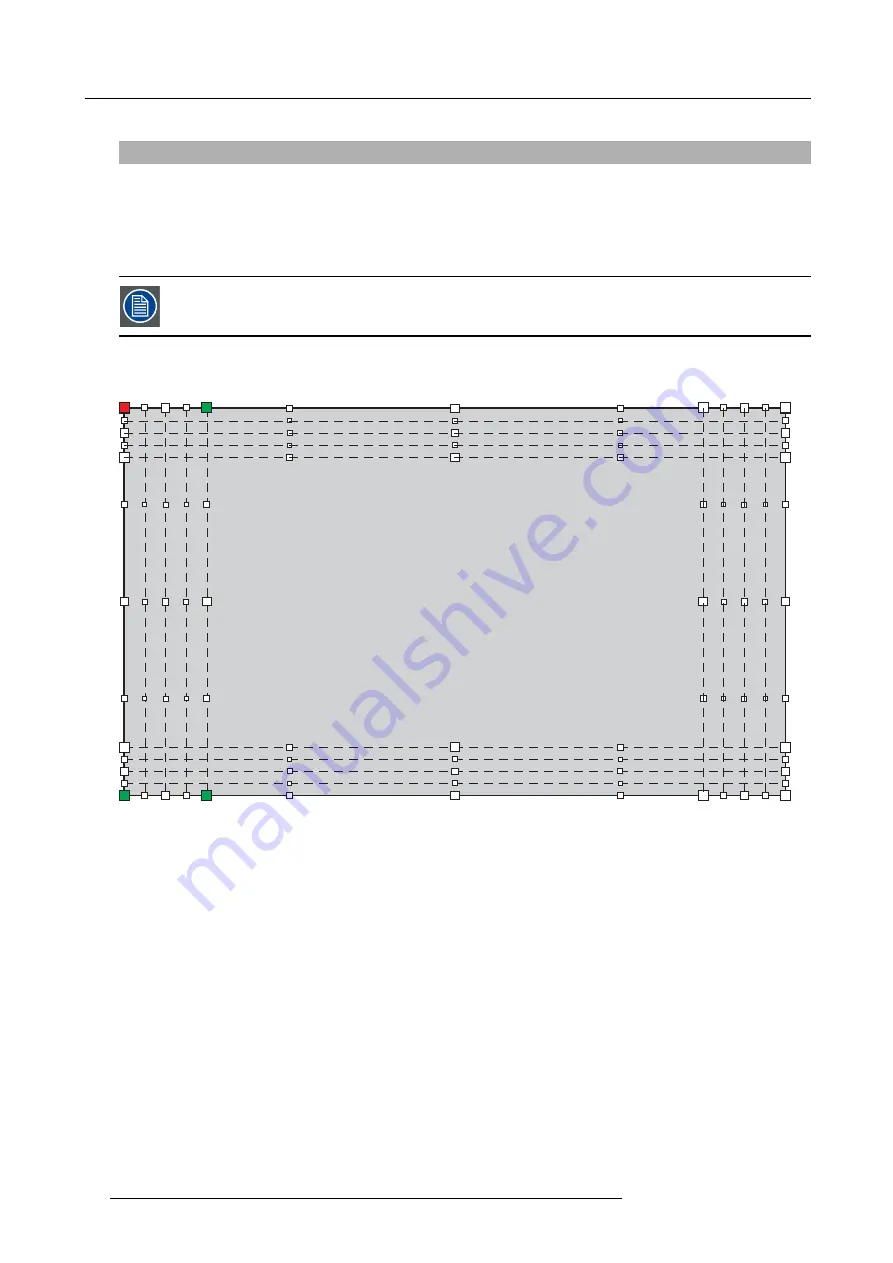
The soft edges are created on the distorted image, i.e. it is available at the borders of the distorted image.
Using the Soft Edge user interface, you can create a Soft Edge area and/or a blanked area on each of the four edges of the image.
Each edge where the blending is to be applied has a
grid
of
anchor points
. Depending on the selected level, the amount of anchor
points can vary from 4 to 25. By default the grid is rectangular, symmetric and it covers 12.5% of the width or height of the image.
Image 11-26
Soft Edge anchor points
The anchor points are numbered from 0 to 24 and can be moved to the desired location to determine the size and shape of the Soft
Edge area on the selected edge. By moving anchor points zero to four, a blanked area is created.
88
R5909057 MCM-50 17/05/2016
Summary of Contents for MCM-50
Page 1: ...MCM 50 User Guide Optimized for F50 R5909057 02 17 05 2016...
Page 8: ...Table of contents 4 R5909057 MCM 50 17 05 2016...
Page 14: ...1 Safety instructions 10 R5909057 MCM 50 17 05 2016...
Page 20: ...3 Packaging 16 R5909057 MCM 50 17 05 2016...
Page 22: ...4 Facility and system requirements Image 4 1 18 R5909057 MCM 50 17 05 2016...
Page 28: ...5 Physical installation and connections 24 R5909057 MCM 50 17 05 2016...
Page 40: ...6 Setup and configuration Image 6 17 36 R5909057 MCM 50 17 05 2016...
Page 58: ...8 OSD Preferences 54 R5909057 MCM 50 17 05 2016...
Page 118: ...11 Expert operation 114 R5909057 MCM 50 17 05 2016...
Page 136: ...13 MCM 50 Tools 132 R5909057 MCM 50 17 05 2016...
Page 144: ...15 RCU Control 140 R5909057 MCM 50 17 05 2016...


