419
8331B–AVR–03/12
Atmel AVR XMEGA AU
32.3.6
Serial Reception
When a start bit is detected, the receiver starts to collect the eight data bits. If the parity bit does
not correspond to the parity of the data bits, a parity error has occurred. If one or both of the stop
bits are low, a frame error has occurred. If the parity bit is correct, and no frame error is detected,
the received data bits are available for the PDI controller.
When the PDI is in TX mode, a BREAK character signaled by the programmer will not be inter-
preted as a BREAK, but will instead cause a generic data collision. When the PDI is in RX mode,
a BREAK character will be recognized as a BREAK. By transmitting two successive BREAK
characters (which must be separated by one or more high bits), the last BREAK character will
always be recognized as a BREAK, regardless of whether the PDI was in TX or RX mode ini-
tially. This is because in TX mode the first BREAK is seen as a collision. The PDI then shifts to
RX mode and sees the second BREAK as break.
32.3.7
Direction Change
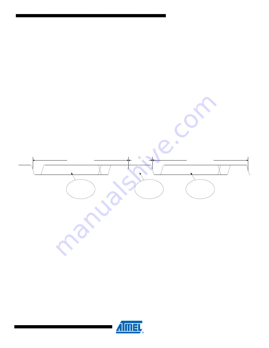
In order to ensure correct timing for half-duplex operation, a guard time mechanism is used.
When the PDI changes from RX mode to TX mode, a configurable number of IDLE bits are
inserted before the start bit is transmitted. The minimum transition time between RX and TX
mode is two IDLE cycles, and these are always inserted. The default guard time value is 128
bits.
Figure 32-7.
PDI direction change by inserting IDLE bits.
The external programmer will loose control of the PDI_DATA line at the point where the PDI
changes from RX to TX mode. The guard time relaxes this critical phase of the communication.
When the programmer changes from RX mode to TX mode, a single IDLE bit, at minimum,
should be inserted before the start bit is transmitted.
32.3.8
Drive Contention and Collision Detection
In order to reduce the effect of drive contention (the PDI and the programmer driving the
PDI_DATA line at the same time), a mechanism for collision detection is used. The mechanism
is based on the way the PDI drives data out on the PDI_DATA line. As shown in
, the PDI output driver is active only when the output value changes (from 0-1 or 1-0).
Hence, if two or more successive bit values are the same, the value is actively driven only on the
first clock cycle. After this point, the PDI output driver is automatically tri-stated, and the
PDI_DATA pin has a bus keeper responsible for keeping the pin value unchanged until the out-
put driver is reenabled due to a change in the bit value.
P
t
S
Sp1
1 DATA character
Sp2
IDLE bits
P
t
S
1 DATA character
Sp1 Sp2
Dir. change
PDI DATA Receive (RX)
PDI DATA Transmit (TX)
Data from
PDI interface
to Programmer
Data from
Programmer to
PDI interface
Guard time
# IDLE bits
inserted


