


Chapter 5 How to Operate BERT
5-6
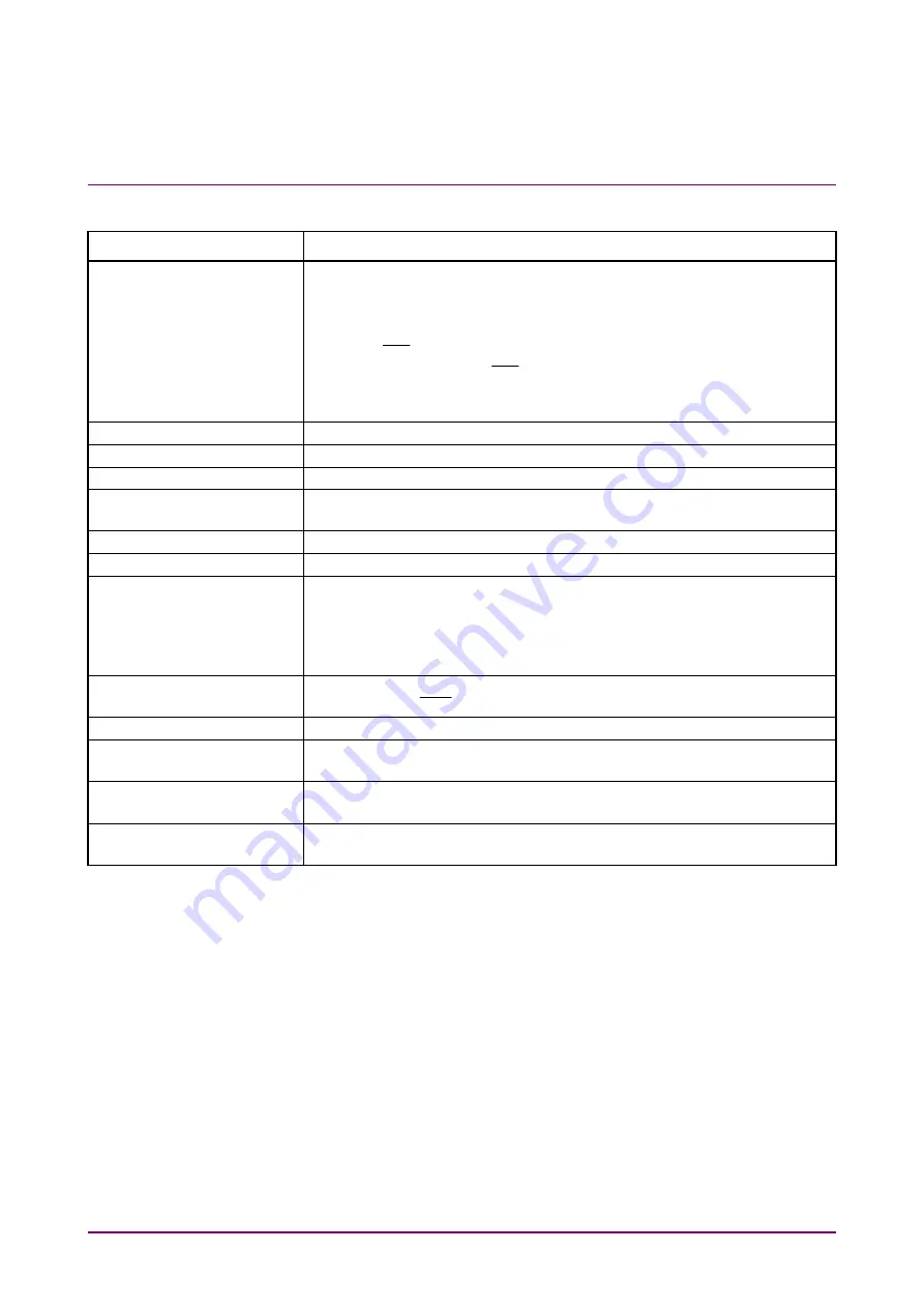
Table 5.2-1 Setting Items of PPG/ED (Cont’d)
Item
Description
Test Pattern*
2
Selects the test pattern by clicking the button.
The polarity of test pattern can be changed by clicking POS or NEG.
The polarity when the test pattern is “1” is shown below:
POS: The voltage of
Data
connector is higher than the voltage of
Data
connector.
NEG: The voltage of
Data
connector is higher than the voltage of
Data
connector.
Set ON at Tracking to set the same test pattern to PPG and ED.
ED Result
Sets the method for displaying the bit error measurement results.
Start Time
Displays the start time of the bit error measurement.
Elapsed Time
Displays the elapsed time of the bit error measurement.
Remaining Time
Displays the remaining time calculated by subtracting the elapsed time
of the bit error measurement from the time set at Gating.
Start/Stop
Stops/starts bit error rate measurement.
History Reset
Deletes the history displays of Sync Loss and Error.
Reference CLK*
1
Selects the clock to be used from the following items:
Internal:
Use the internal clock based on the internal 10 MHz oscillator.
Ext Clk In:
Use the external clock input from the
Ext Clk In
connector.
Sync Out*
1
Selects the clock source and division ratio for the signal output to the
Sync Out
and
Sync
Out
connector
Clk Out*
1
Selects the clock source for the signal output to the
Clk Out
connector.
Error Addition
When Insert Error is clicked, bit errors are inserted in the test pattern,
and the indicator on the right is lit in red for one second.
Gating Cycle*
2
Selects the bit error measurement method by clicking the button.
Set the time of single bit error measurement.
Current Setting
On updates the results display while BER measurement is in
progress.
*2: This is set as common in Ch 1 to Ch 4 when Ch Tracking is on in
MP2110A-014.
Summary of Contents for BERTWave Series
Page 26: ...VI...
Page 74: ...Chapter 1 Outline 1 48...
Page 166: ...Chapter 4 Screen Operation 4 24...
Page 210: ...Chapter 6 How to Operate Sampling Scope 6 16 Figure 6 2 2 4 Switching Graph Display...
Page 309: ...6 9 Measuring Waveform 6 115 6 How to Operate Sampling Scope Figure 6 9 5 1 Marker Display...
Page 322: ...Chapter 6 How to Operate Sampling Scope 6 128...
Page 380: ...Chapter 8 Maintenance 8 14 7 Click Reinstall Windows 8 Click Yes...
Page 432: ...Appendix A Specifications A 36...
Page 458: ...Appendix D Performance Test Record Form D 12...
Page 466: ...Index Index 6...