


230 Actual signals and parameters
4002
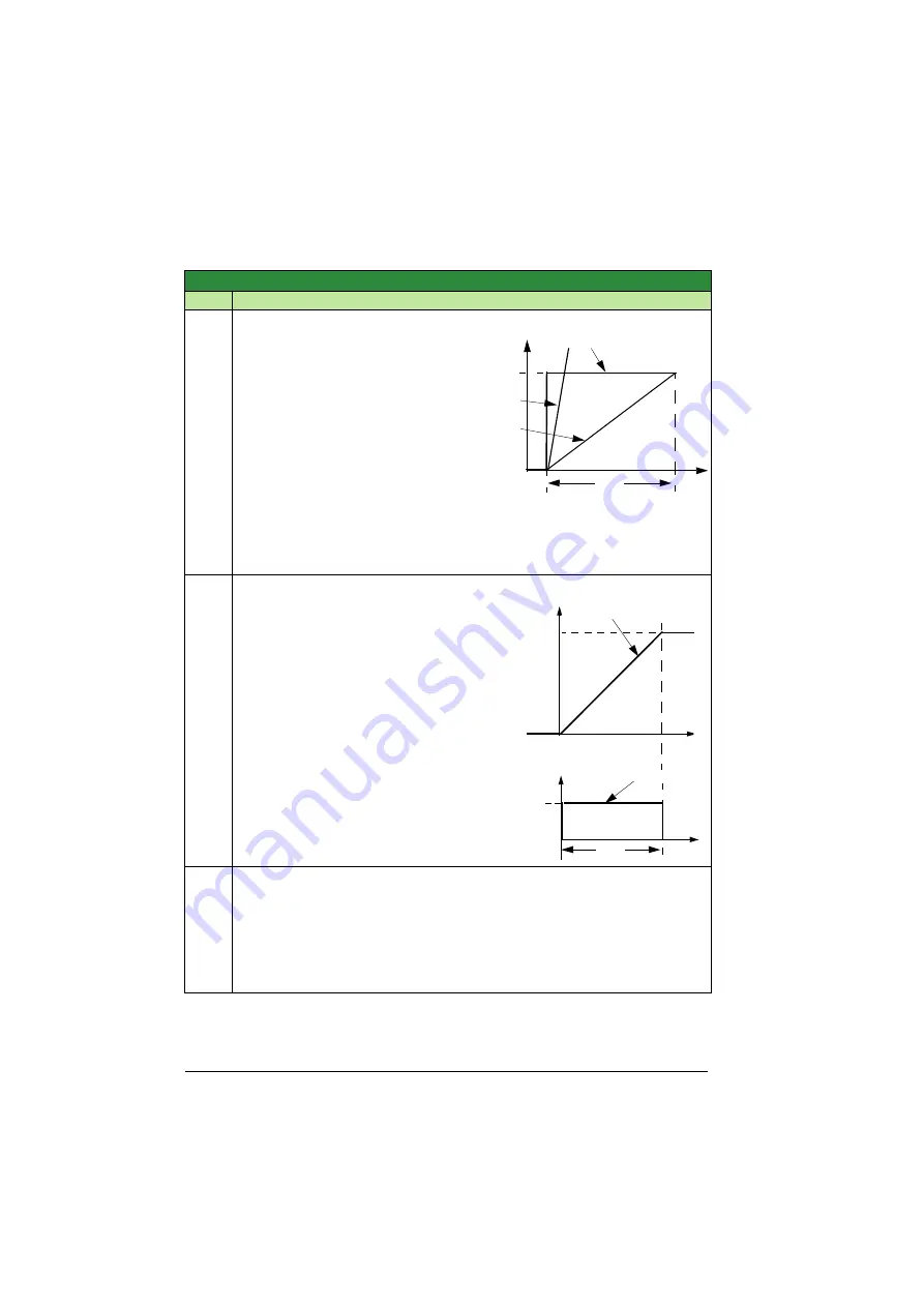
INTEGRATION TIME
0.0 … 3600.0 s
0.1 s
3.0 s
Defines the PID controller’s
integration time.
Integration time is, by definition, is
the time required to increase the
output by the error value:
• Error value is constant and 100%.
• Gain = 1.
• Integration time of 1 second
denotes that a 100% change is
achieved in 1 second.
0.0 = NOT SEL Disables integration
(I-part of controller).
0.1 … 3600.0 = Integration time
(seconds).
for adjustment procedure.
4003
DERIVATION TIME
0.0 … 10.0 s
0.1 s
0.0 s
Defines the PID controller’s derivation time.
• You can add the derivative of the error to
the PID controller output. The derivative is
the error value’s rate of change. For
example, if the process error value
changes linearly, the derivative is a
constant added to the PID controller
output.
• Error-derivative is filtered with a 1-pole
filter. The time constant of the filter is
defined by parameter
0.0 = NOT SEL Disables the error-derivative
part of the PID controller output
0.1 … 10.0 = Derivation time (seconds)
4004
PID DERIV FILTER
0.0 … 10.0 s
0.1 s
0.1 s
Defines the filter time constant for the error-derivative part of the PID controller output.
• Before being added to the PID controller output, the error-derivative is filtered with a
1-pole filter.
• Increasing the filter time smooths the error-derivative, reducing noise.
0.0 = NOT SEL Disables the error-derivative filter.
0.1 … 10.0 = Filter time constant (seconds).
Group 40: Process PID set 1
Code
Description
Range
Resolution
Default
S
t
A
B
A = Error
B = Error value step
C = Controller output with Gain = 1
D = Controller output with Gain = 10
D (
= 10)
C (
= 1)
4002
t
100%
Gain
Process error value
D-part of controller output
PID output
Error
t
0%
4003
Summary of Contents for ACS320 series
Page 1: ...ABB drives User s manual ACS320 drives 0 5 to 30 hp ...
Page 4: ......
Page 18: ...18 Safety ...
Page 28: ...28 Operation principle and hardware description ...
Page 56: ...56 Electrical installation ...
Page 142: ...142 Program features Connection diagram example ACS320 xx xxxx x ...
Page 282: ...282 Actual signals and parameters ...
Page 358: ...358 Fieldbus control ...
Page 376: ...376 Fault tracing ...
Page 382: ...382 Maintenance and hardware diagnostics ...
Page 407: ...Dimension drawings 407 Frame size R2 NEMA 1 Frame size R2 IP20 NEMA 1 3AUA0000051097 A ...
Page 409: ...Dimension drawings 409 Frame size R3 NEMA 1 Frame size R3 IP20 NEMA 1 3AUA0000051118 A ...
Page 411: ...Dimension drawings 411 Frame size R4 NEMA 1 Frame size R4 IP20 NEMA 1 3AUA0000051133 A ...
Page 412: ...412 Dimension drawings ...
Page 413: ...Index Numerics A B C D E F G H I K L M N O P R S T ...


