3.2.4 Diagnosis
DANGER!
The diagnosis data is not safety-relevant and, thus, shall not be used in safety application program for
execution of safety functions.
during the start-up of Safety I/O modules.
AI581-S
UP 24VDC 2W
4SAI
Safety Analog Input
3.8 UP
3.9 ZP
3.4
3.7
3.0 I2-
3.1 FE
3.2 I3-
3.3 FE
3.5
3.6
ERR1
2.9ZP
2.8UP
2.3
2.4
2.5
2.1
2.7
2.6
2.2I1+
2.0I0+
ERR2
4.9ZP
4.8UP
4.7
4.2I3+
4.0I2+
4.6
4.5
4.4
4.3
4.1
PWR
1.9ZP
1.8UP
1.7
1.4
1.0I0-
1.2I1-
1.3FE
1.1FE
1.5
1.6
ADDR
x10H
ADDR
x01H
C
4
3
B
2
A
1
9
0
8
F
7
E
6
D
5
C
4
3
B
2
A
1
9
0
8
F
7
E
6
D
5
1
2
4
3
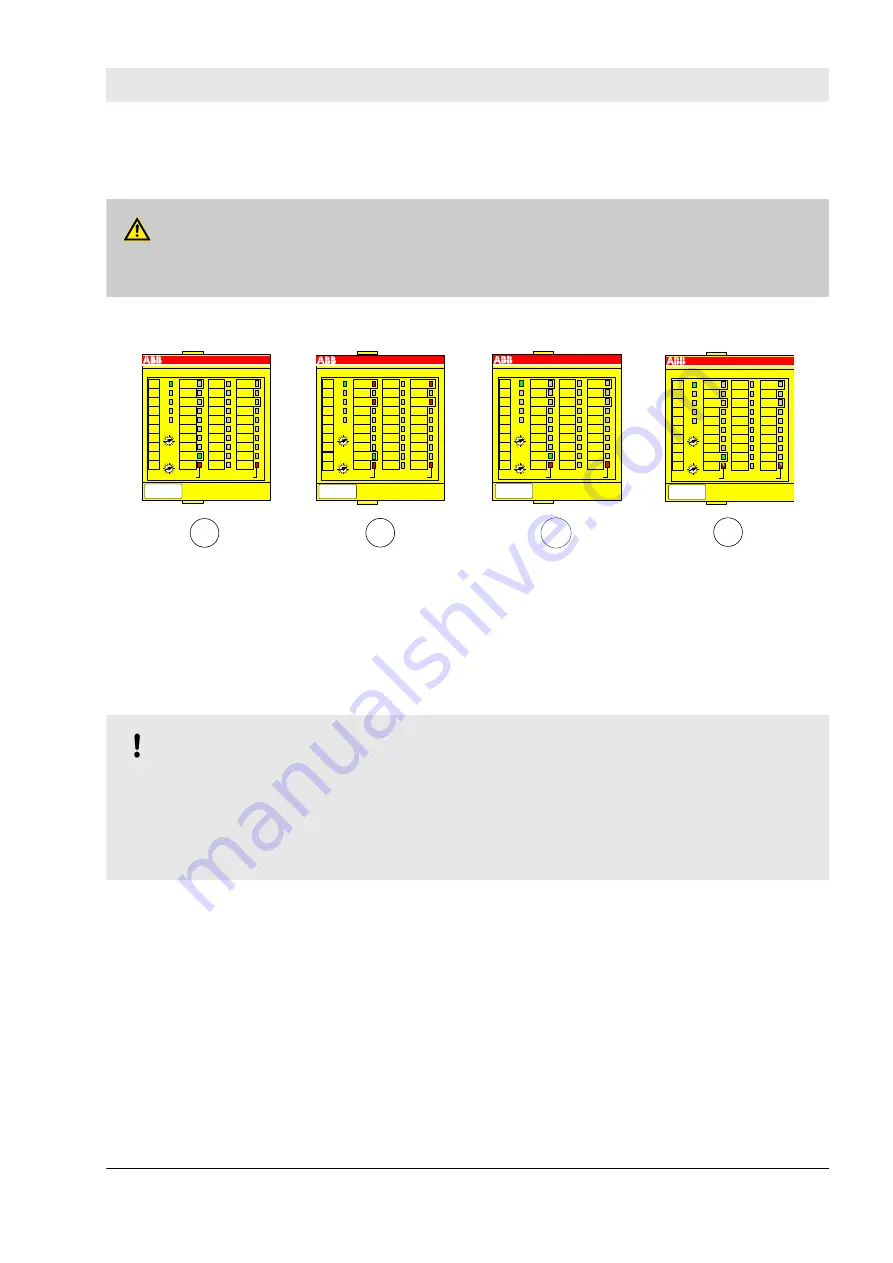
Fig. 15: LED states of Safety I/O modules during start-up (example with AI581-S module)
1
State 1 – Hardware reset and initialisation
2
State 2 – LED test
3
State 3 – End state of initialization
4
State 4 – Parameterisation is complete, but no
PROFIsafe communication yet
NOTICE!
External errors (wiring or sensor errors) in Safety I/O modules lead to the channel passivation (“0”
values are delivered). As soon as an external error is fixed and this is recognized by internal Safety
I/O module tests, Safety I/O module channels request an acknowledgement for their reintegration to
the normal safety process control mode. The user can acknowledge such channels using dedicated
channel bits (
Chapter 4.3.5 “Instantiation and configuration of safety modules/Definition of variable
Safety I/O module error messages are aggregated together with other module error messages in PM5xx
CPU. The following two tables include a list of error messages related to Safety I/O modules.
AC500-S Safety Modules
Generic Safety I/O module behaviour > Diagnosis
30.03.2017
AC500-S
71


