


3
AC500-S Safety Modules
3.1 SM560-S Safety CPU
Elements of the module
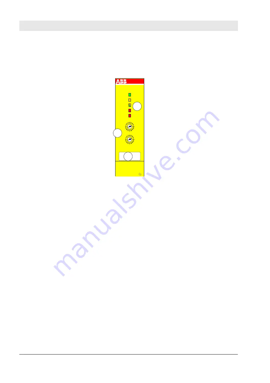
SM560-S
DIAG
PWR
RUN
I-ERR
E-ERR
ADDR
x10H
ADDR
x01H
1
2
3
Fig. 5: SM560-S
1
Five LEDs for status display
2
Rotary switch for address/configuration setting
3
Label
3.1.1 Purpose
SM560-S is the Safety CPU for up to SIL3 (IEC 61508 ed. 2 and IEC 62061) and PL e (ISO 13849) safety
applications. The Safety CPU is mounted on the left side of the Non-safety CPU, e.g., PM573, PM583,
PM592 or others with the firmware version from V2.2.1, on the same Terminal Base. The communication
between the Non-safety CPU and the Safety CPU takes place through the internal communication bus,
which is integrated in the Terminal Base. The data interchange is realized by a dual-port RAM.
Depending on the used Terminal Base, 1 … 4 Communication Modules (e.g., CM579–PNIO, etc.) can be
simultaneously employed at one Non-safety CPU. However, only one SM560-S Safety CPU can be operated
simultaneously at one Non-safety CPU.
The Safety CPU is programmed and configured via the dual-port RAM using safety system configurator and
CoDeSys Safety programming environment, which are a part of the PS501 Control Builder Plus V2.2.1 (or
newer) / ABB Automation Builder 1.0 (or newer) software.
The configuration of SM560-S is saved non-volatile in a Flash EPROM.
3.1.2 Functionality
3.1.2.1
Overview
SM560-S Safety CPU for AC500 PLCs is available from version V2.2.1 (or newer) of the PS501 Control
Builder Plus software / version 1.0 (or newer) of the ABB Automation Builder software and can be used with
Non-safety CPUs (PM573, PM583, PM592 or others with the firmware version from V2.2.1 and with suitable
TB5xx units). Power supply is provided via the coupler interface of the Terminal Base.
AC500-S Safety Modules
SM560-S Safety CPU > Functionality
30.03.2017
AC500-S
32


