


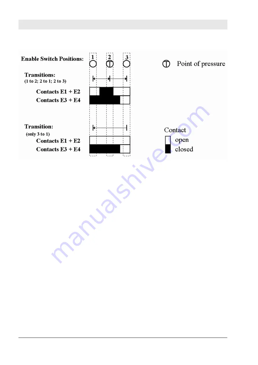
Fig. 117: Switch positions
The signal from E1+E2 must be connected to the S_EnableSwitchCh1 parameter. The signal from E3+E4
must be connected to the S_EnableSwitchCh2 parameter. The position of the enable switch is detected in
the FB using this signal sequence.
The transition from position 2 to 3 can be different from shown here.
The switching direction (position 1 => position 2/position 3 => position 2) can be detected in the FB using the
defined signal sequence of the enable switch contacts. The suspension of safeguarding can only be enabled
by the FB after a move from position 1 to position 2. Other switching directions or positions may not be used
to enable the suspension of safeguarding. This measure meets the requirements of EN 60204 Section
9.2.5.8.
In order to meet the requirements of DIN EN 60204 Section 9.2.4, the user shall use a suitable switching
device. In addition, the user must ensure that the relevant operating mode (DIN EN 60204 Section 9.2.3) is
selected in the application (automatic operation must be disabled in this operating mode using appropriate
measures).
The operating mode is usually specified using an operating mode selection switch in conjunction with
SF_ModeSelector FB and SF_SafeRequest or SF_SafelyLimitedSpeed FB.
The SF_EnableSwitch FB processes the confirmation of the "safe mode" state via the "S_SafetyActive"
parameter. On implementation in an application of the safe mode without confirmation, a static TRUE signal
is connected to the "S_SafetyActive" parameter.
The S_AutoReset input shall only be activated if it is ensured that no hazardous situation can occur when the
PES is started.
Configuration and programming
AC500-S Libraries > SafetyBlocks_PLCopen_AC500_v22.lib
30.03.2017
AC500-S
368


