background image


1.Name and Function of Each Block - 1.3.Operation Panel 

1WMPD4004444 

19 

1.3. 

Operation Panel 


SD


PRINT 


TRIG 


START 


STOP 


DISK 


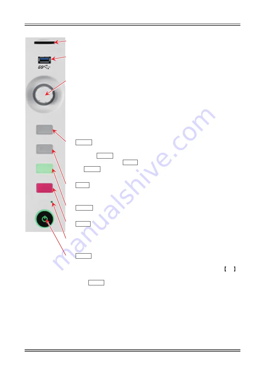
(1)  SD card slot 

Used to save recorded data to an SD memory card, etc. 

(2)  USB 

Used to save recorded data to USB memory, etc. in the same manner as to an SD 
memory card. 

(3)  Rotary knob 

Used to select the module ranges and setting values by turning it clockwise and 
counterclockwise.   
When the rotary knob is enabled, the area around the knob lights in the blue color 
of the normal mode.   
Push the rotary knob to switch the area around the knob to the orange of the fine 
adjustment mode.   
Push it again to return the area around the knob to the blue color of the normal 
mode. 

(4)   PRINT   key 

Outputs the waveform recording to the printer. 
Press the   PRINT   key to start waveform recording and again to end recording.   
You can also press the   STOP   key to end recording. Press and hold 
the   PRINT   key to output a copy of the screen (screenshot) to a printer, which 
can be saved to the main unit or external media in the .png file format. 

(5)   TRIG   key 

Outputs a forced trigger during measurement.   
The TRIG LED lights when a trigger is detected. 

(6)   START   key 

Starts measurement. 

(7)   STOP   key 

Stops measurement. 

(8)  DISK access light 

The LED lights when accessing the internal SSD (for reading or writing). 

(9)   Power   switch 

Turns the power of the main unit on/off.   
The [Shut down] screen is displayed when turning the power off. Press the  OK  
button to complete the shutdown process.   
If this   Power   switch is pressed again while the [Shut down] screen is displayed, 
the product automatically shuts down. 


Summary of Contents for RA3100 Omniace

Page 1: ...RA3100 Omniace Instruction Manual 1WMPD4004444...

Page 2: ...damages or loss of income caused by the operation of this device or any direct indirect special or inevitable damages caused by defects in the product even if there is notice that the corresponding d...

Page 3: ...s instruction manual explains cautions and methods for handling the RA3100 and its optional input modules Please read this manual before operating this instrument If you encounter any problems in the...

Page 4: ...umber Quantity Remarks Omniace main unit RA3100 1 AC 100 V to 240 V Simple Operation Manual 1WMPD4004445 1 The manual is described cautions on use and operations methods Instruction Manual CD ROM 1WME...

Page 5: ...s of life or may result in light injury or physical damage if this equipment is misused due to neglect of a Warning CAUTION This indicates a condition or practice that could result in light injury or...

Page 6: ...ecifications Do not use it with a Measurement Category that exceeds the module specifications Connection of Input Signals Be sure to ground the grounding terminal of this product before connecting to...

Page 7: ...ollowing operating environments Operating temperature range 0 to 40 C Operating humidity range 35 to 85 RH without condensation Do not use this product at the following locations In addition carefully...

Page 8: ...te product failure When storing recording paper for an extended period of time before recording remove the recording paper from the main unit and insert it in a plastic bag or as is if it is still in...

Page 9: ...le after the shut down process is complete Use on a Network Please consult your network administrator to make sure that other tasks are not affected by connecting this product to the network Computer...

Page 10: ...creen with a finger Example Used for selecting or setting screen keys A swipe is the act of pressing the screen with a finger and moving it in a specific direction Example Used on screens such as the...

Page 11: ...ollowing cases Damage or faults caused by incorrect use Damage or faults caused by fire earthquake traffic accident or other natural disasters Damage or faults caused by a repair or modification that...

Page 12: ...g 27 2 2 Turning the Power On Off 32 2 2 1 Connecting the AC Power Cable 32 2 2 2 Turning On the Power 32 2 2 3 Confirming Normal Startup 33 2 2 4 Setup Date and Time 34 2 2 5 Preparing for More Preci...

Page 13: ...72 7 3 X Y Waveform 73 7 3 1 X Y Display Setup 73 7 3 2 X Y Control 74 7 4 FFT Analysis 75 8 SETUP DETAILS 77 8 1 Recording Setup 77 8 1 1 Recording 77 8 1 2 Channel List 78 8 1 3 Sheet Setup 80 8 1 4...

Page 14: ...e Input Channel 123 9 6 4 Standard Clock Output 123 9 6 5 Measurement Setup 123 9 6 6 Reference Materials 124 9 6 7 Options 127 10 APPENDIX 128 10 1 Sampling Data Format 128 10 1 1 Normal Sampling 128...

Page 15: ...Setup 152 12 2 12 Other Setup Maintenance Operation History Version Management 153 12 3 Module Specifications 154 12 3 1 Two Channel Voltage Module RA30 101 154 12 3 2 Four Channel Voltage Module RA30...

Page 16: ...his product consists of the following blocks 1 1 Name of Each Block Front view Handle retractable SD card slot Display Block USB Operation panel Power switch Corner pad USB LAN Screen lock Video outpu...

Page 17: ...1 Name and Function of Each Block 1 1 Name of Each Block 1WMPD4004444 17 Top view Handle retractable Rear view Stand...

Page 18: ...ch in out to enlarge or reduce the waveform or scroll the waveform Side menu Used to switch the display screen configure the various input modules configure the recording conditions configure recordin...

Page 19: ...PRINT key Outputs the waveform recording to the printer Press the PRINT key to start waveform recording and again to end recording You can also press the STOP key to end recording Press and hold the...

Page 20: ...The video output terminal 6 COM port Used to perform remote control from an external PC via RS 232C 1 5 Input Module Block Slot 1 Slot 2 Slot 3 Slot 4 Slot 5 Slot 6 Slot 7 Slot 8 Slot 9 Up to nine mod...

Page 21: ...el list Sheet Printer Main unit setup Record management Image management Environment Display Other setup Maintenance Operation history Version management 8 SSD Displays the remaining space on the inte...

Page 22: ...speed Selects the sampling speed The speed table differs according to the recording device Printer recording 1 kS s 100 ms div to 10 S s 10 min div SSD recording 1 MS s 100 s div to 10 S s 10 min div...

Page 23: ...y recording 20 MS s 5 s div to 10 S s 10 min div 2 Data format Displays either NORMAL or P P as the format for the recorded data Only P P is available for printer recording Only NORMAL is available fo...

Page 24: ...llution Degree of 2 Use this product in the following operating environments Operating temperature range 0 to 40 C Operating humidity range 35 to 85 RH without condensation Do not use this product at...

Page 25: ...n The measurement category of this module is category II CAT II 300 V The module cannot be used with measurement categories that exceed its specifications such as CAT III and CAT II 600 V Connect the...

Page 26: ...ng the guide rails The module type should be on the operation panel side Step 4 Tighten the screws on both edges with a Phillips head screwdriver No 2 Removal Procedure Step 1 Turn the power OFF Step...

Page 27: ...d as paper feed problems may occur or the print quality may be Do not use the portion of the new roll where the recording paper tip is covered with tape as colors may not be printed normally on this a...

Page 28: ...nding direction carefully Push it in so that the thermally sensitive side is faced up Insert the paper holders into the guide of the printer block Step 4 Feed the recording paper to the recording pape...

Page 29: ...paper stock box Z fold paper adapter Approx 200 g Z fold paper adapter The procedures for loading the Z fold paper are explained as follows Step 1 Place the product on top of the paper case With the...

Page 30: ...Z fold paper case Step 3 Open the printer block by raising the lever of the printer cover After opening the printer cover insert the paper pulled out from the case into the opening under the printer c...

Page 31: ...paper threaded into the Z fold paper adapter from above the platen roller of the printer block black roller from the recording paper outlet of the printer bar and pull it out about 10 cm Platen rolle...

Page 32: ...t equipped with a protective conductor pin the product is automatically grounded Do not use an extension cable without protective grounding Do not use this product when protective grounding cannot be...

Page 33: ...e power turns on NOTE Standby current flows to this product when the AC power cable is connected to the power outlet Remove the power cable when the product will not be used for an extended period of...

Page 34: ...4Setup Measurement This completes the preparations for measurement 2 2 6 Turning Off the Power Step 1 When the Power key on the operation panel is pressed while the power is on the shut down process...

Page 35: ...display range and the sampling speed in the time axis direction Set the recording device and sample speed according to the target for measurement Chapter 4 3 Set the sampling speed and the recording...

Page 36: ...p 3 When the Meas range key is tapped in the channel setup sub menu the border of the key turns orange the area around the rotary knob turns blue and the rotary knob can be used to change the setting...

Page 37: ...displayed channel Step 6 To change the display slot of the input module swipe the channel setup sub menu left or right or tap the or key on the top Step 7 Next connect the insulation BNC cable standa...

Page 38: ...e anti aliasing filter of the input channel on or off 10 Disp pos Specify the position of the waveform monitor to display the specified range of the waveform display area Specified as a percentage ind...

Page 39: ...nal as it cancels the DC offset of the signal GND Connects the channel input to GND without connecting the input signal inside the channel Enables the input GND level to be checked with waveform monit...

Page 40: ...so reduces the resolution of the data The display range and display position settings can be used to change the display scale and display position of the waveform amplitude direction without reducing...

Page 41: ...ximum Display range Display minimum Display position NOTE If the sensitivity of the measurement range is increased to enlarge the amplitude the amplitude of the input signal will only become a little...

Page 42: ...age waveform recorded on the selected recording device is displayed on the left edge of the control bar An image of the waveform recorded on the selected device is displayed on the waveform monitor Ta...

Page 43: ...ng term data to the SSD at medium speed NORMAL or P P can be selected for the recorded data When recorded with NORMAL data FFT or X Y analysis is possible in addition to standard Y T waveforms For P P...

Page 44: ...d with the data count set in the pre trigger and memory block size which represents a single recording operation When the number of blocks to record is set to a multiple number recording starts for th...

Page 45: ...igger is detected when the value enters the range of the upper limit value or lower limit value of the trigger level OUT WIN The trigger is detected when the value leaves the range of the upper limit...

Page 46: ...used 3 Trigger detection when the INTO WIN OUT WIN trigger is selected for detection Trigger OUT WIN Trigger INTO WIN Upper threshold Input signal Lower threshold Trigger OUT WIN Trigger INTO WIN Trig...

Page 47: ...T Trigger filter 5 3 Pre Trigger When performing memory recording a pre trigger can be set to adjust the recording length before and after the trigger detection point in the memory block Trigger detec...

Page 48: ...D recording Memory recording Trigger occurred Trigger occurred Trigger occurred 5 4 1 Start Trigger Setup Step 1 Tap the CH key on the side menu to display the channel setup sub menu Step 2 Tap the Tr...

Page 49: ...playback The PRINT key can also be pressed in the monitor display state to perform real time waveform printing pen recording via the internal printer Monitor Pen recording PRINT key POWER key ON STOP...

Page 50: ...WMPD4004444 6 2 Monitor Display and Pen Recording 6 2 1 Monitor Display Function Tap the recording device selection in the side menu to display the image waveform recorded on the selected device on th...

Page 51: ...eform on the waveform monitor You can also use one finger to drag the screen up down left or right to move the display area Trigger Synchronization When the recording device is set to MEMORY a trigger...

Page 52: ...see 4 3 1 Setup the Sampling Speed X Y Waveform and FFT Analysis When SSD is selected as the recording device and NORMAL is selected as the data format FFT analysis and the X Y waveform display for th...

Page 53: ...hile executing pen recording Press the PRINT key on the operation panel to start waveform recording with the printer Pen Recording Mode When PRINTER is selected as the recording device tap the menu on...

Page 54: ...art speed Step 1 Tap the SETUP key on the side menu to display the Setup menu Step 2 Tap Printer in Recording setup to display the printer related menu Step 3 Tap Chart speed on the top of the Printer...

Page 55: ...PRINT key to end waveform printing Recording ends after printing the footer 6 2 3 Setup and Printing Annotations This product has a function for printing header annotation and footer text before durin...

Page 56: ...aracter 4 The Delete all key clears all the input text 5 The Insert row key inserts one row in the specified row position 6 The Delete row key deletes the specified row and brings the lower rows up 7...

Page 57: ...the OK key to save the text to external media with the specified file name Saved with the specified file name NOTE The import output folder of external media is fixed to drive name of external media...

Page 58: ...TUP Recording setup Printer Printing to display the Printing setup screen where the information printed while printing the waveform with printer recording can be set 1 2 3 4 5 6 7 8 1 Header Prints th...

Page 59: ...is enabled for a device the data recorded to each device is recorded to the SSD while it is recorded to the device For the printer the waveform data P P values printed to the recording paper are also...

Page 60: ...be enabled disabled When enabled the waveform of the specified sheet is printed from the printer while saving the data of the printer recording When disabled printing to the printer is not performed 8...

Page 61: ...nel is pressed Memory recording records the input data to memory when the trigger is occurred after recording starts Data recording is not performed unless a trigger is detected 2 Start time Press STA...

Page 62: ...time in the recording setup elapses or the STOP key on the operation panel is pressed 4 Interval N times Interval time Press START key 1 time N times End recording Recording time Recording time Durin...

Page 63: ...e recording setup elapses or the STOP key on the operation panel is pressed 6 Start trigger Interval N times Start trigger occurs Interval time START trigger occurs Press START key 1 time N times End...

Page 64: ...e time set in Start time then continues recording for the time set in Recording time Measurement repeats at the interval set in Interval time 8 Start time Start trigger Interval N times Start trigger...

Page 65: ...ART key Press STOP key During Record Recording time SSD recording When the START key on the operation panel is pressed recording to the various devices starts and continues until the STOP key on the o...

Page 66: ...s updated with the latest waveform and used block count Ending Recording Recording ends when the recording time set in Recording time elapses or when the STOP key on the operation panel is pressed The...

Page 67: ...is still in the recording state MEASURE is selected on the side menu and the waveform frame remains red Scroll the waveform monitor to the right in this state to scroll the waveform back and check the...

Page 68: ...recording device Waveform format Data selection key 7 1 Select Recorded Data Tap the DATA selection key on the control bar to display the recorded data list indicated below Select the data and tap the...

Page 69: ...r and selecting a device in the side menu the waveform for each device when recording is displayed Select recording device Control bar switch key 7 2 1 Playback Screen Operations Enlarging Reducing th...

Page 70: ...E THUMBNAIL CURSOR PENREC WAVE Select THUMBNAIL to display the thumbnail waveform of the channel set in the recording setup menu in the control bar area You can also tap the thumbnail display channel...

Page 71: ...or B position X is the time from the first of cursor B and Y is the data value at the position of cursor B A B Information on the difference between cursors A and B X is the time between cursors A and...

Page 72: ...ts the channel to display in the cursor position information Tap the channel selection key to display the channel selection screen indicated below where you can select the channel to display in the cu...

Page 73: ...ay 7 3 1X Y Display Settings 7 3 2 X Y Control By tapping the Single Quad key for display control the X Y waveform can be displayed as four waveforms overlaid on a single screen or as four separate sc...

Page 74: ...n to configure the X axis and Y axis channel settings for each waveform 7 All pen down Resumes waveform display when it has been paused with All pen up 8 Dot Line Switches between rendering the X Y wa...

Page 75: ...swiping the analysis results area to the left or right 2 Meas ON OFF Enables disables the execution of FFT analysis 3 FFT settings Tap this key to switch to the FFT settings screen to 2 Meas ON OFF c...

Page 76: ...al scaling is disabled the Y axis is automatically set based on the analysis results When enabled the upper limit value and lower limit value of the Y axis scale can be set manually Channel setting Se...

Page 77: ...tings from Settings in the side menu 8 1 Recording Setup Configure Recording Channel list Sheet and Printer Tap a settings category to display the detailed settings screen for that category 8 1 1 Reco...

Page 78: ...tion of the selected channels You can tap Select all on the top right to select all the channels CH Displays the slot number and channel number connected with a hyphen Module Displays the model of the...

Page 79: ...conversion with the primary function y ax b Conversion1 is gain Conversion2 is offset 2 pt Converts two input voltages to two target physical quantities Conversion1 is the first physical conversion v...

Page 80: ...urement range of the input module Tap to change the range L P F Displays the low pass filter setting Tap to change the filter A A F Displays the antialiasing filter setting Tap to change the filter 8...

Page 81: ...eader Text CH name before printing the waveform Select Text CH name Text CH name or OFF as the information to print before the waveform Annotation Enables or disables the printing of annotation text t...

Page 82: ...g ends after printing the footer Date Sets the recording date time to print above the waveform Recording name Sets the recording name to print above the waveform Top Date Bottom Test name Time axis Se...

Page 83: ...he text to print The setting method is the same for each For details see 6 2 3 Setting and Printing Annotations Chart speed Set the user defined chart speed displayed on the control bar when PRINTER i...

Page 84: ...or managing data recorded with this product is explained below Tap Record management in the main unit settings in SETUP on the side menu to display the Record management screen A list of the recorded...

Page 85: ...i on or setting restoration Tap the selection field again to deselect the data Step 1 Select all Selects all the recorded data Step 2 Release all Deselects all the data Step 3 Delete Deletes the selec...

Page 86: ...recording conditions can be exported to external media by itself to easily restore recording condition settings 8 2 2 Export Backing Up Recorded Data Connect the external storage media such as SD memo...

Page 87: ...xternal media to the main unit When importing place a check mark i n t he recorded dat a l i stf orext ernalm edi a onthe right and tap the Import key in the center Place a check mark on the data to i...

Page 88: ...on field on the left of the list to display t o sel ectt hatdat a as t he t argetf oroperation Tap the selection field again to deselect the data 1 Select all Selects all the image data 2 Release all...

Page 89: ...8 Setup Details 8 2 Main Unit Setup 1WMPD4004444 89 Place a check mark i n t he sel ect i on f i el d oft he dat a t o export Image data list on internal SSD Image data list on external media...

Page 90: ...ment setup screen 1 2 3 4 5 6 The functions of each item are indicated below 1 PC name Sets the name of this product Tap the name field to display the PC name dialog box for changing the name Press an...

Page 91: ...period of time Select OFF 1 minutes 5 minutes 10 minutes 30 minutes or 60 minutes Select OFF to always display the monitor 6 Display brightness Changes the screen brightness Set a value between 1 and...

Page 92: ...e device make sure to set a different address when connecting two or more of this product 3 Subnet mask The value that defines the IP address range subnet Normally set class C Class C 255 255 255 000...

Page 93: ...data Fixed to 8 bits 3 Stop bits The stop bits in one byte of data Select 1 or 2 bits 4 Parity The parity bit for one byte of data Select none odd even mark or space 5 Flow control The flow control of...

Page 94: ...p Details 8 3 Other setupOther 94 1WMPD4004444 8 3 Other setup Configure display Maintenance Operation history and Version management Tap a settings category to display the details screen for that cat...

Page 95: ...e deterioration in the LCD may cause pixel defects The head temperature may be high after performing printer recording for an extended period of time which can cause an error In this case check again...

Page 96: ...o emit a beep to confirm that the buzzer works 7 LED Check the state of the main unit using the LED on the operation panel Use the color around the rotary knob to check the fine coarse setting PRINT O...

Page 97: ...ry in the other settings to display the history of the last 100 operations 8 3 3 Version Management Tap Version management in the other settings to display and update the version of this product For i...

Page 98: ...Select the channel in the slot 4 Meas ON OFF ON Measure and record the input signal 5 Color Change the display color of the waveform monitor 6 Coupling Switch the input signal coupling in the order D...

Page 99: ...f the actual input signal including the DC and AC component AC Measures the AC component of the input signal only Set this when you want to measure only the amplitude of an AC signal as it cancels the...

Page 100: ...n Display Area Disp range The display width in the amplitude direction of the waveform display area on the waveform monitor Disp pos Specify the position of the waveform monitor to display the specifi...

Page 101: ...amage may be caused if the voltage is exceeded 1 Input cable The input connectors for CH1 and CH2 are insulated BNC connectors Do not connect metallic BNC plugs as they may damage the connectors or ca...

Page 102: ...t 7 Meas range Change the measurement range of the input channel When this key is tapped the rotary knob is enabled the LED lights up and the range can be selected by turning the knob 1 2 2 3 3 4 5 6...

Page 103: ...e input sensitivity can be changed with the Meas range key 7 in the channel setup sub menu The value displayed for the measurement range RANGE indicates the input measurement maximum value and corresp...

Page 104: ...to variation in the DC offset voltage Execute zero cancellation to minimize these errors To perform zero cancellation tap the Zero adjust key 14 after waiting for a warm up period of 60 minutes NOTE T...

Page 105: ...module RA3100 main unit Slots Common Settings Interface 1ch H L 200 V AC DC 300 V AC DC 300 V AC DC 300 V 2ch H L 200 V 3ch H L 200 V 200 V 4ch H L Between each input and the chassis to ground AC DC...

Page 106: ...ignal coupling in the order DC GND AC Tap the key and turn the rotary knob to select 7 Meas range Change the measurement range of the input channel When this key is tapped the rotary knob is enabled t...

Page 107: ...input signal only Set this when you want to measure only the amplitude of an AC signal as it cancels the DC offset of the signal GND Connects the channel input to GND without connecting the input sign...

Page 108: ...ange Disp min Set the display lower limit value of the bottom of the display range Step 6 Execute zero adjust After turning on the power changes in the surrounding temperature as time elapses change t...

Page 109: ...avoid damage to devices and enable safe measurement Increased device heat and input voltage may damage the signal source and device 3 Maximum rated voltage to ground CAUTION Use it within the range of...

Page 110: ...g voltage probe for recording the existence of 100 V or 200 V system voltage and the 1540S and 1543S voltage conversion probes for recording voltage increases and decreases for AC 100 V systems and AC...

Page 111: ...the eight channels in CHA and CHB 11 Sheet Displays the sheet number when using monitor display or printer recording for CHA or CHB You can tap SHEET to change the sheet number 9 4 3 Measurement Setu...

Page 112: ...16 channels but eight channels are grouped in CHA and CHB respectively The input trigger and waveform display settings are set separately for CHA and CHB The connectors are also separate for CHA and C...

Page 113: ...nput L AGND is connected internally 9 4 5 Options 1 Connection cables and terminal blocks The following cables terminal blocks and probes are provided for signal input Name type Shape characteristics...

Page 114: ...03 One input 9 5 Two Channel Temperature Module RA30 106 9 5 1 Overview This module is a two channel temperature measurement module that can set three measurement ranges for each thermocouple TC and p...

Page 115: ...t1000 0 1 mA 3 Meas range Set the temperature range to measure Three types of ranges can be selected for each sensor type 4 Refresh data Select low speed 1 s medium speed 100 ms or high speed 1 5 ms a...

Page 116: ...ms the data is updated 10 times per second This provides more stable measurement accuracy than with high speed With high speed 1 5 ms the response speed is faster and quickly changing temperatures can...

Page 117: ...r connector insert it into the connector of the front panel The terminal names of the input connectors are indicated on the left side of the panel as and S A terminal Connect the side wire of the ther...

Page 118: ...cision and little variation or deterioration Used as standard thermocouple TC The electromotive force characteristic has poor linearity Poor linearity of electromotive force characteristic Cannot meas...

Page 119: ...etector RTD sensor Use three equal length cables for RTD extension in order to match the resistance values Ensure the wire resistance is 10 or less per wire Connect a single RTD to a single channel Wi...

Page 120: ...JC when measuring thermocouple TC Reference junction compensation is required when measuring the thermocouple TC and can be switched between internal and external compensation with this module Interna...

Page 121: ...ise error will occur from the power consumption in the thermocouple TC resistance because a current of 0 5 A is constantly supplied It can be disabled when performing standard measurement to reduce th...

Page 122: ...input module The remote function includes both remote input for control from an external device and remote output for performing synchronized operation with another RA3100 and this product acting as t...

Page 123: ...he response speed of the remote input signal In noisy environments select Low speed to perform control with a filter The effective pulse width of the input signal is as follows For high speed response...

Page 124: ...ring recording A7 NC B7 IGND A8 EXT SMPL IN B8 IGND SMPL External synchronization sampling The data sampling and printer recording of this product is performed with this sampling clock A9 TRIG IN B9 I...

Page 125: ...INT signal of remote input to the PRINT output A5 EXT SMPL OUT B5 IGND External synchronization sampling Output the SMPL signal of remote input to the EXT SMPL signal output A6 TRIG OUT B6 IGND Trigge...

Page 126: ...ote control synchronized operation Remote control cable for connecting units RA30 505 5 3 Synchronization signal for AC strain Remote control Remote control synchronized operation Synchronization sign...

Page 127: ...cable for connecting units RA30 505 For connecting RA3100 20P 14P Length 2 m RA30 112 2 Pin layout Pin layout of RA30 112 input connectors and correspondence chart of remote control cables and termin...

Page 128: ...mpling period the waveform reproducibility may drop and lead to the unexpected loss of pulses Raising the sampling speed improves the waveform reproducibility but increases the recorded data 10 1 2 P...

Page 129: ...on function converts the voltage values output from a sensor etc to a physical quantity for direct reading This product has two conversion methods Both methods perform the same conversion as indicated...

Page 130: ...ion Real number part Lin Rel R Imaginary number part Lin Img I Amplitude Lin Amp R2 I2 Logarithmic amplitude Log Amp 20 log R2 I2 Phase Phase tan 1 I R RMS Spectrum One Signal Analysis The frequency d...

Page 131: ...ectrum Two Signal Analysis The cross power spectrum derives the power between two signals It is derived as the product of the linear spectrum Gx of the signal to compare and the complex conjugate Gx o...

Page 132: ...sses a comparison of the power caused by the input signal of the transfer system and the total output power It is derived from the cross power spectrum Gyx input reference power spectrum Gxx and outpu...

Page 133: ...led Enabled Logarithmic amplitude Log Amp Disabled Enabled Enabled Power spectrum density Amplitude Lin Amp Disabled Enabled Enabled Logarithmic amplitude Log Amp Disabled Enabled Enabled Cross power...

Page 134: ...part Lin Img eu Amplitude Lin Amp eu Logarithmic amplitude Log Amp db Phase Phase deg RMS spectrum Real number part Lin Rel eu Imaginary number part Lin Img eu Amplitude Lin Amp eu Logarithmic amplitu...

Page 135: ...ger Trigger mode OFF By trigger source Trigger channel OFF Analog input module Detection UP Threshold 0 Trigger filter 0 s Logic module Detection BIT OR Bit pattern All bits disabled Trigger filter 0...

Page 136: ...setup Set manually IP address 192 168 0 1 Subnet mask 255 255 255 0 Default gateway 0 0 0 0 DNS server address setup Set manually Preferred DNS server 0 0 0 0 Alternate DNS server 0 0 0 0 RS 232C Baud...

Page 137: ...life of the thermal head Red is printed on the recording paper when the recording paper is running low The remaining paper monitor PAPER is displayed on the side menu of the monitor Follow these to r...

Page 138: ...with a temperature of 25 C or less and humidity of 70 RH or less When using a file folder make sure that it is made of a material that does not include plasticizer such as polyethylene or polypropyle...

Page 139: ...SD can be checked in Life remaining and Health in SSD on the Maintenance screen When the life remaining is close to 0 please contact our sales representative to replace the SSD 11 3 Display Cleaning W...

Page 140: ...ears at 23 C If the clock resets every time the power is turned on the battery may need to be replaced In this case please contact our sales representative 11 8 Fan Replacement If the internal fan sto...

Page 141: ...Do not continuously print solid black areas Real time waveform printing is disabled in the recording settings Enable real time waveform printing in the recording settings and start recording SSD recor...

Page 142: ...10 S min 1 kS s 100 mm s to 10 S min 1 mm min Sampling accuracy 10 ppm max At all available temperature ranges Printer block Thermal printer Recording width Chart speed Chart speed accuracy Recording...

Page 143: ...elevation 2000 m or lower Warmup time 60 minutes or longer Operating environment Temperature humidity 0 to 40 C 35 to 85 RH or less without condensation Storage environment Temperature humidity 20 to...

Page 144: ...3 The Measurement Category categorizes a testing or measurement circuit according to the type of main power circuit intended to be connected for testing or measurement and differs according to the mo...

Page 145: ...s Sampling speed Differs according to recording device Maximum recording time 100 days 12 2 2 SSD Recording Item Specifications Function Records input data directly to the internal SSD Recording devic...

Page 146: ...s number of memory divisions Points 2 GW 1 Divided into 1 to 200 user defined blocks The number of data items per channel that can be recorded to a recording block 2 kW to 2 GW selected in step 1 2 5...

Page 147: ...le when the optional remote control module is installed 12 2 5 Trigger Function Basic trigger function Item Specifications Trigger function Start trigger Memory trigger Start trigger for recording ope...

Page 148: ...to be displayed for a maximum of two channels Y T waveform display Display width 20 div x 20 div Time axis T axis Amplitude axis Y axis Display area 1 div 100 samples 1 div 1 10 RANGE with display ra...

Page 149: ...en position Zero position Pinch in out Renders the X Y waveform with dots or lines Input signal scale display of X axis and Y axis Grid display of waveform area Displays the input signal position Disp...

Page 150: ...ording when performing measurement sheet selection enable disable real time waveform printing during measurement SSD Enable disable SSD recording when performing measurement Memory Enable disable memo...

Page 151: ...ecorded data and sets it in the main unit Image Management Image list Displays a list of the images recorded to this product Choice Selects images in the list Multiple data can be selected Select all...

Page 152: ...ve or manually set the IP address When manually setting the IP address the IP address subnet mask and default gateway can be manually set IP address Set the IP address Subnet mask Set the subnet mask...

Page 153: ...rints a test patter from the printer Printer state check System motor head temperature printer cover recording paper Buzzer Controls the buzzer on off to check the buzzer Panel keys Press the panel ke...

Page 154: ...teristics 3 Hz 30 Hz 300 Hz 3 kHz OFF 1 6 dB 1 dB Secondary vessel Anti aliasing filter A A F Cutoff frequency Attenuation 20 40 80 200 400 800 2k 4k 8k 20k 40 kHz OFF 66 dB or less at 1 5 times the c...

Page 155: ...off frequency Characteristics 3 Hz 30 Hz 300 Hz 3 kHz disabled 1 6 dB 1 dB Secondary vessel shape Input conversion noise 5 mVp p max 1 V range input short circuit A D conversion A D resolution Samplin...

Page 156: ...1 dB with L P F disabled Low pass filter L P F Cutoff frequency 3 Hz 30 Hz 300 Hz 3 kHz OFF 3 dB 1 dB Input conversion noise 2 mVp p max 0 1 V range input short circuit A D conversion A D resolution...

Page 157: ...t Select one of three levels H L is linked 250 or less 1 5 k or less 3 0 k or less 2 0 k or more 5 0 k or more 9 0 k or more 0 5 mA typ load resistance 0 to 18 k Response pulse 2 s or more Maximum all...

Page 158: ...re range LFD Switchable on off Measurement range RANGE Measurement probability Type Measurement range Measurement range C Measurement probability K 200 C 600 C 1370 C 200 to 200 200 to 600 200 to 1370...

Page 159: ...000 200 C 400 C 850 C 200 to 200 200 to 400 200 to 850 Temperature coefficient Measurement probability x 0 1 C Item Specifications Common mode rejection ratio 50 60 Hz Signal source resistance 100 or...

Page 160: ...al input signal and output signal from the RA3100 main unit Control signals START STOP MARK FEED PRINT TRIG Output level High level 3 8 V to 5 0 V Low level 0 V to 0 5 V active low Output pulse width...

Page 161: ...io 50 5 Withstand voltage AC 300 V 1 minute input between output and chassis Maximum rated voltage to ground AC DC 42 V Usage environment Temperature 0 to 40 C humidity 35 to 85 RH or less without con...

Page 162: ...13 Optional Parts 13 1 List of Cables 162 1WMPD4004444 12 4 Exterior 12 4 1 Main Unit Exterior 394 199 410 334...

Page 163: ...12 Specifications 12 4 Exterior 1WMPD4004444 163 12 4 2 Two Channel Voltage Module RA30 101 Exterior...

Page 164: ...13 Optional Parts 13 1 List of Cables 164 1WMPD4004444 12 4 3 Four Channel Voltage Module RA30 102 Exterior...

Page 165: ...12 Specifications 12 4 Exterior 1WMPD4004444 165 12 4 4 Two Channel Voltage Module RA30 103 Exterior...

Page 166: ...13 Optional Parts 13 1 List of Cables 166 1WMPD4004444 12 4 5 16 Channel Logic Module RA30 105 Exterior...

Page 167: ...12 Specifications 12 4 Exterior 1WMPD4004444 167 12 4 6 Two Channel Temperature Module RA30 106 Exterior...

Page 168: ...13 Optional Parts 13 1 List of Cables 168 1WMPD4004444 12 4 7 Remote Control Module RA30 112 Exterior...

Page 169: ...channel logic cable IC clip RA30 501 For logic input 4 channels x 2 shared ground 1 5 m RA30 105 8 channel logic cable alligator clip RA30 502 For logic input 4 channels x 2 1 5 m RA30 105 8 channel...

Page 170: ...s 13 3 Accessory 170 1WMPD4004444 13 2 List of Probes Clamp Meters Name type Shape Remarks Floating voltage probe 1539S 4 input RA30 105 Voltage variation probe 1540S AC 100 120 V 1543S AC 220 240 V 1...

Page 171: ...e Name Shape Remarks RA30 551 Z fold paper box Z fold paper adapter Including RA12 301 RA30 552 Dedicated delivery box RA23 183 Carrying case RA30 555 Temperature sensor connectors RA30 106 Temperatur...

Page 172: ...5 rolls box 0511 3167 5 rolls YPS108 Recording paper Paper roll 219 5 mm x 30 m Perforated 150 mm pitch Remaining display print 300 mm pitch 99 to 00 5 rolls box 0511 3166 5 rolls YPS112 Recording pa...

Page 173: ...13 Optional Parts 13 2 List of Probes Clamp Meters 1WMPD4004444 173 MEMO...

Page 174: ...13 Optional Parts 13 4 List of Spare Parts 174 1WMPD4004444 MEMO...

Page 175: ...Omniace RA3100 Instruction Manual 1WMPD4004444 1st Edition...

Page 176: ...550420 Fax 44 1235 550485 A D AUSTRALASIA PTY LTD 32 Dew Street Thebarton South Australia 5031 AUSTRALIA Telephone 61 8 8301 8100 Fax 61 8 8352 7409 A D KOREA Limited 6 33 817 07331 817 Manhattan Bld...

Reviews: