


Sensor properties
Excitation
voltage
U
EXC
Bridge resistance R
B
120
Ω
350
Ω
700
Ω
1000
Ω
2.5V
X
X
X
X
5V
X
X
X
X
7.5V
X
X
X
X
10V
X
X
X
X
12V
X
X
X
X
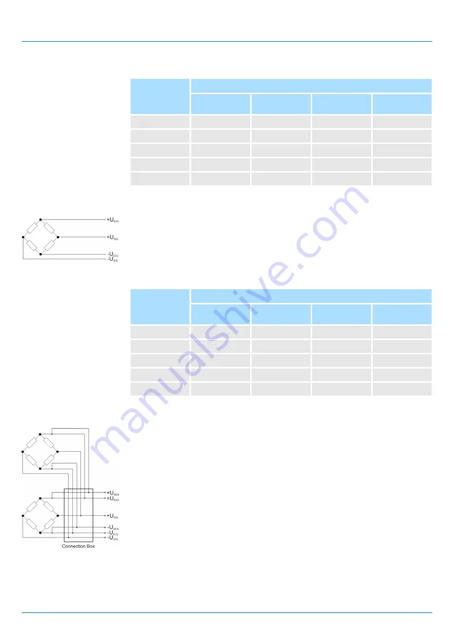
With the 4 wire measurement the U
SEN
pins are not connected. With this operating mode
there is an internal connection between U
EXC
and U
SEN
.
The following table shows the properties of the sensors, which can be used with the 4
wire measurement.
Sensor properties
Excitation
voltage
U
EXC
Bridge resistance R
B
120
Ω
350
Ω
700
Ω
1000
Ω
2.5V
X
X
X
X
5V
X
X
X
X
7.5V
X
X
X
X
10V
X
X
X
X
12V
X
X
X
X
Normally large mechanical loads are divided to multiple strain gauge DMS load cells and
these parallel connected via a connection box to the strain gauge DMS module. Please
consider that the load cells are aligned together for this operating mode and approved by
the manufacturer. And the current feed capacity of the transducer electronic should not
be overloaded. The current feed capacity is derived from the number of parallel-con-
nected load cells, excitation voltage U
EXC
and the bridge resistance.
Depending on the excitation voltage U
EXC
, I
EXC
may not exceed a maximum current:
n
2.5V: maximum current 120mA
n
5V: maximum current 120mA
n
7.5V: maximum current 100mA
n
10V: maximum current 90mA
n
12V: maximum current 80mA
For the calculation of I
EXC
the following formula is used:
4 wire measurement
Parallel connection
VIPA System SLIO
Analog Input
031-1CA20 - AI 1x16(24)Bit Strain gauge (DMS) > Connection variants
HB300 | SM-AIO | | en | 17-05
174