Copyright © Siemens AG 2016. All rights reserved
8
ERTEC 200P-2 Manual
Technical data subject to change
Version
1.0
2.3.6.3
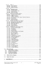
Address Mapping ...............................................................................................................189
2.3.6.4
Register Description ...........................................................................................................190
2.3.7
Peripheral Interface ...............................................................................................................197
2.3.7.1
2.3.7.1.1
Address Mapping .........................................................................................................199
2.3.7.1.2
Register Description .....................................................................................................203
2.3.8
2.3.8.1
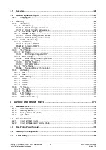
PN-IP Interfaces ................................................................................................................230
2.3.8.1.1
AHB Interface...............................................................................................................230
2.3.8.1.2
Interrupt Management ..................................................................................................230
2.3.8.1.3
PN-PLL (incl. 3x Application Timer Blocks) ...................................................................232
2.3.8.1.4
EDC in PN-IP RAMs ....................................................................................................234
2.3.8.1.5
Recommended Parameter Assignment for ERTEC 200P .............................................234
2.3.8.2
Ethernet PHY (integrated) ..................................................................................................235
2.3.8.2.1
Status of the integrated PHY ........................................................................................236
2.3.9
CRU (Clock and Reset Unit) ..................................................................................................236
2.3.9.1
2.3.9.2
Clock Generation and Distribution ......................................................................................236
2.3.9.2.1
PLL Clock Generation ..................................................................................................237
2.3.9.2.2
Clock Source for the PHYs and Ethernet MACs............................................................238
2.3.9.2.3
Clock Source for JTAG .................................................................................................238
2.3.9.3
Clock Monitoring ................................................................................................................238
2.3.9.3.1
Lock Timer 1 ................................................................................................................238
2.3.9.3.2
Lock Timer 2 ................................................................................................................238
2.3.9.3.3
Lock Monitor ................................................................................................................239
2.3.9.4
2.3.9.4.1
Asynchronous PowerOn Reset .....................................................................................243
2.3.9.4.2
Asynchronous Hardware Reset ....................................................................................244
2.3.9.4.3
Asynchronous JTAG Reset ..........................................................................................244
2.3.9.4.4
Asynchronous ARM926 Watchdog Reset .....................................................................245
2.3.9.4.5
Asynchronous Software Reset for ERTEC 200P (Without PN-IP) .................................245
2.3.9.4.6
Asynchronous Software Reset for PN-IP ......................................................................245
2.3.9.4.7
Asynchronous Software Reset for the ARM926EJ-S Core ............................................246
2.3.9.4.8
Synchronous Software Reset (PN-IP, PER-IF, Host Interface) ......................................246
2.3.10
APB Peripherals ....................................................................................................................247
2.3.10.1
2.3.10.1.1
Operating Principle of the RC Filter ............................................................................250
2.3.10.1.2
Address Mapping .......................................................................................................251
2.3.10.1.3
Register Description ...................................................................................................253
2.3.10.2
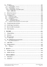
ARM926 Watchdog ........................................................................................................260
2.3.10.2.1
2.3.10.2.2
Block diagram ............................................................................................................260
2.3.10.2.3
Signal waveforms .......................................................................................................263
2.3.10.2.4
Write protection of the watchdog register ....................................................................264
2.3.10.2.5
Starting the Watchdog ................................................................................................264
2.3.10.2.6
2.3.10.2.7
Address Mapping .......................................................................................................265
2.3.10.2.8
Register Description ...................................................................................................266
2.3.10.3
2.3.10.3.1
2.3.10.3.2
TIMER_TOP functionality ...........................................................................................270
2.3.10.3.3
Timer module .............................................................................................................273
2.3.10.3.4
Overview of the count modes .....................................................................................280
2.3.10.3.5
Timing requirements ..................................................................................................281
2.3.10.3.6
Operating rules ..........................................................................................................282
2.3.10.3.7
Connections on ERTEC 200P Toplevel ......................................................................283
2.3.10.3.8
Address Mapping .......................................................................................................285
2.3.10.3.9
Register Description ...................................................................................................286
2.3.10.4
2.3.10.4.1
Function Description ..................................................................................................303
2.3.10.4.2
Application Information ...............................................................................................303
2.3.10.4.3
Address Mapping .......................................................................................................303
2.3.10.4.4
Register Description ...................................................................................................304
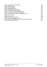
Содержание ERTEC 200P
Страница 1: ...ERTEC 200P 2 Enhanced Real Time Ethernet Controller Manual ...
Страница 309: ...Copyright Siemens AG 2016 All rights reserved 309 ERTEC 200P 2 Manual Technical data subject to change Version 1 0 ...
Страница 492: ...Copyright Siemens AG 2016 All rights reserved 492 ERTEC 200P 2 Manual Technical data subject to change Version 1 0 ...


