Copyright © Siemens AG 2016. All rights reserved
249
ERTEC 200P-2 Manual
Technical data subject to change
Version 1.0
The input signal is filtered following two-stage synchronization (this is required to avoid
metastable states). The channel-specific filter is implemented as a 5-bit up/down counter
that counts up when the input signal is "high" and down when the input signal is "low".
The counter value after RESET is '00h' (load value).
As the input channels for the digital input modules are operated separately, each input
signal requires its own counter. These counters must enable different, channel-specific
filter time settings. The filter time is selected in the 'FILT_Delay_x registers', which in line
with the settings select different clock sources on a channel-specific basis (mode 3) or
select input signal synchronization only without RC filtering (mode 2). In mode 2, the
doubly synchronized input signal D_IN_SYN is connected straight to the output signal
D_IN_Delay and not through the counter register. In mode 1, the input signal D_IN is
connected straight to the output signal D_IN_Delay, bypassing the synchronization stage
and counter register. Dynamic FILT_Delay_x toggling is not permitted during operation.
Parameter assignment is in the initialization phase only.
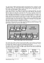
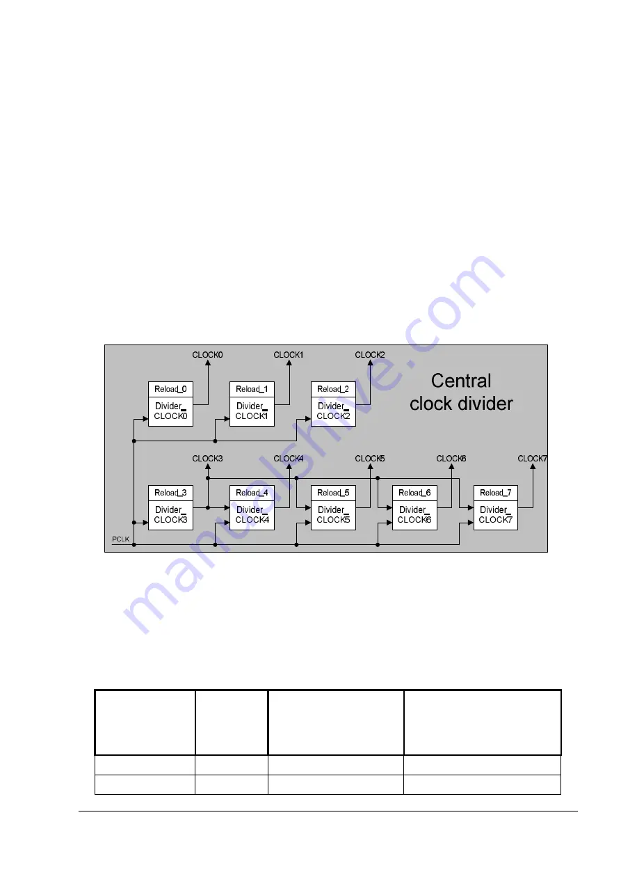
The clock sources (CLOCK0 to CLOCK7) are generated for all channels by a central
clock divider. The base clock for all divider stages is the APB clock PCLK (125 MHz). The
block diagram below shows how the system operates:
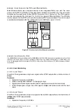
Figure 32:
Block diagram of the central clock divider
The central clock divider consists of several divider stages, some of which are cascaded.
The division factors are set for each divider stage with a dedicated 'FILT_Reload_x' regis-
ter. Dynamic FILT_Reload_x toggling is not permitted during runtime.
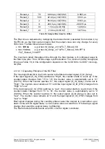
The division factors of the individual stages of cascaded dividers must be multiplied to
calculate the "total division factor". The table below shows the filter times achieved with
sample division factors at 125 MHz:
Parameter
register
FILT_Reload_x
Sample
division
factor
Filter time
(without 2-stage
synchr.)
t
delay
Minimum
filter time
(filter time – CLOCK
jitter)
Reload_0
8
1.024 µs (CLOCK0)
0.960 s
Reload_1
40
5.12 µs (CLOCK1)
4.80 s
Содержание ERTEC 200P
Страница 1: ...ERTEC 200P 2 Enhanced Real Time Ethernet Controller Manual ...
Страница 309: ...Copyright Siemens AG 2016 All rights reserved 309 ERTEC 200P 2 Manual Technical data subject to change Version 1 0 ...
Страница 492: ...Copyright Siemens AG 2016 All rights reserved 492 ERTEC 200P 2 Manual Technical data subject to change Version 1 0 ...


