Copyright © Siemens AG 2016. All rights reserved
336
ERTEC 200P-2 Manual
Technical data subject to change
Version 1.0
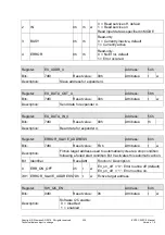
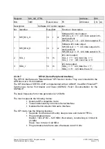
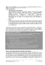
The SPI module can be controlled by ARM926 or by the GDMA controller. Access from
the external host over the host interface is also possible, but interrupts are not supported
in this case. The module FIFO interrupt is not activated or deactivated until 4 entries have
been made (in line with the transfer direction).
As the FIFO submodule for GDMA operation cannot be disabled, a module modification
is required for independent GDMA operation (no ARM926 activity). For the receiver, the
internal SPI module signal 'SPI1/2_SSPRXDMA, corresponding to RNE: Receive FIFO
not empty' is sent to the module border to display the receive FIFO status for the GDMA.
For the transmitter, the interrupt signal 'SPI1/2_SSPTXINTR, corresponding to the state:
Transmit FIFO is half full or less' is used to display the transmit FIFO status for the
GDMA.
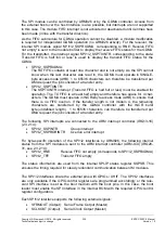
SPI1/2_SSPRXDMA:
The RX FIFO contains at least one character and is not empty. As the SPI cannot
know when the last character was read in, the GDMA must operate in SINGLE-
byte access mode (AHB). 1 to 65536 characters can therefore be transferred per
DMA request; the job consists of a transfer entry.
SPI1/2_SSPTXINTR:
The SSPTXINTR interrupt (Transmit FIFO is half full or less) must be enabled for
operation. The TX FIFO is at least half empty and therefore has space for 4 char-
acters. The GDMA must operate in INCR4-byte access mode (AHB) to ensure that
there is no FIFO overrun. If the transfer length is not modulo 4, the remaining
characters are transferred by the GDMA controller with the INCR burst
byte (undefined length). 1 to 65536 characters can therefore be transferred per
DMA request; the job consists of a transfer entry.
The following SPI interrupts are connected to the ARM interrupt controller (IRQ13-16)
(2.3.2.14):
SPI1/2_SSPINTR
Group interrupt
SPI1/2_SSPRORINTR
Overrun error interrupt
For byte-specific operation of the SPI1/2 interfaces by ARM926, the following internal
status from the SPI modules is sent to the ARM interrupt controller (ARM-ICU) (IRQ28-
31, see 2.3.2.14):
SPI1/2_RNE
Receive FIFO not empty (corresponds to SPI1/2_SSPRXDMA)
SPI1/2_TFE
Transmit FIFO empty
The status information are used from the internal SPI-IP status register SSPSR. This
ensures the timing required for steady redundant communication between IM modules.
The SPI1/2 interfaces share the external pins with GPIOs / XHIF. The SPI1/2 interfaces
are only available if the GPIO control registers are programmed accordingly or the rele-
vant SPI interface is set as the boot medium with the boot pins. In this case, the boot
loader must enable the SPI interface in the internal ROM with the required GPIO control
register configuration.
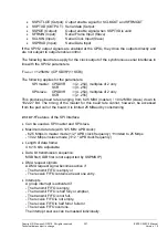
Each SPI1/2 interface supports the following external signals:
SFRMOUT (Output): Serial Frame Output (Master)
SCLKOUT (Output): Serial Clock Output (Master)
Содержание ERTEC 200P
Страница 1: ...ERTEC 200P 2 Enhanced Real Time Ethernet Controller Manual ...
Страница 309: ...Copyright Siemens AG 2016 All rights reserved 309 ERTEC 200P 2 Manual Technical data subject to change Version 1 0 ...
Страница 492: ...Copyright Siemens AG 2016 All rights reserved 492 ERTEC 200P 2 Manual Technical data subject to change Version 1 0 ...

