Copyright © Siemens AG 2016. All rights reserved
158
ERTEC 200P-2 Manual
Technical data subject to change
Version 1.0
o
The default setting is slow timing for booting purposes
o
A maximum of 64 MByte address area for each chip select
o
Acknowledgement delay monitoring for external components can be set by
software
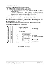
The EMC interface only supports “Little Endian” mode. The block schematic of the EMC
module is shown in chapter 2.3.5.1.
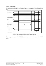
2.3.5.1 Block Diagram of the EMC
Figure 9: EMC Block Diagram
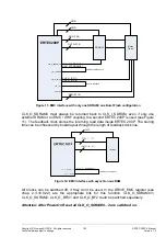
Note: External memory system is a representation for all types of memories, which can
be connected to the EMC. Forwarding the AHB clock to the external memory system via
a BIDI buffer, which feeds back the clock to the receive part of the EMC module is only
an example application. For high clock frequencies (> 100 MHz) it is recommended to us
separated input-/output-buffers to feedback the external memory clock.
The EMC interface can only be driven by 1,8V (necessary for mobile SDRAM). The EMC
IO pads are separated from the other IOs and have their own power supply (VDD1,8V
and GND). This supply ring contains all 77 IO Pads of the EMC interface. So the EMC
can work with 1,8V and the other IOs (e.g. GPIOs) with 3,3V.
The driver strength of the 1,8V EMC pads is 12mA after PowerOn Reset by default.
Содержание ERTEC 200P
Страница 1: ...ERTEC 200P 2 Enhanced Real Time Ethernet Controller Manual ...
Страница 309: ...Copyright Siemens AG 2016 All rights reserved 309 ERTEC 200P 2 Manual Technical data subject to change Version 1 0 ...
Страница 492: ...Copyright Siemens AG 2016 All rights reserved 492 ERTEC 200P 2 Manual Technical data subject to change Version 1 0 ...

