Copyright © Siemens AG 2016. All rights reserved
160
ERTEC 200P-2 Manual
Technical data subject to change
Version 1.0
SDRAM
Burst
flash
ADR (14:0)
DATA (31:0)
CLK_O_SDRAM(0)
ADR (23:15)
CMD
CMD
CLK_O_SDRAM(1)
CLK_I_SDRAM
CLK_O_SDRAM(2:0)
SDRAM CLK feedback
CLK_O_BF (1)
CLK_O_BF (0)
BF CLK feedback
CLK_I_BF
CLK_O_BF(2:0)
XRDY_BF
ERTEC200P
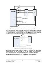
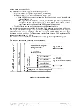
Figure 11: EMC interface with only one SDRAM / one Burst Flash configuration
CLK_O_SDRAM0 must always be returned back to CLK_I_SDRAM, even if only one
external SRAM or an EMC / XHIF coupling to a second ERTEC 200P is used (see Figure
11). The feedback clock stores the incoming read data inside ERTEC 200P. The storing
time can be influenced by boardlayout through the length of feedbackclock line.
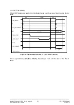
Figure 12: EMC interface with asynchronous RAM
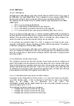
All Clocks can be switched off, if they don't be used. In the DRIVE_EMC register (see
chap. 2.3.10.9.22) are the appropriate bits for this function. CLK_O_SDRAM0/1,
CLK_O_SDRAM2, CLK_O_BF0/1 and CLK_O_BF2 could be switched separately.
Attention: After PowerOn Reset all CLK_O_SDRAM0…2 are switched on.
Содержание ERTEC 200P
Страница 1: ...ERTEC 200P 2 Enhanced Real Time Ethernet Controller Manual ...
Страница 309: ...Copyright Siemens AG 2016 All rights reserved 309 ERTEC 200P 2 Manual Technical data subject to change Version 1 0 ...
Страница 492: ...Copyright Siemens AG 2016 All rights reserved 492 ERTEC 200P 2 Manual Technical data subject to change Version 1 0 ...


