Copyright © Siemens AG 2016. All rights reserved
54
ERTEC 200P-2 Manual
Technical data subject to change
Version 1.0
module and clear the register (ERR_LOCK = '0'). The SW must subsequently reset the
MODUL_ACCESS_ERROR register in the SCRB by writing the value 0x0.
In the event of read access to unassigned addresses in AHB modules, an AHB error
response is also generated on the AHB (PN-IP, PER-IF). This triggers an exception in
ARM926EJ-S.ARM-ICU (ARM926 Interrupt Controller)
2.3.2.6 Overview
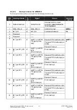
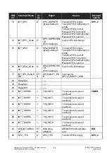
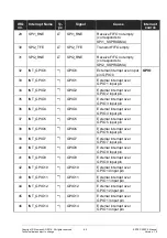
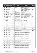
The Interrupt Controller Unit (ICU),see chapter 7.2), supports both IRQ (Interrupt Re-
quest) and FIQ (Fast Interrupt Request) interrupt levels which are named in the following
IRQ subblock and FIQ subblock. This overview chapter describes the functionality using
the IRQ subblock. The following sections discuss the differences between the IRQ sub-
block and the FIQ subblock.
The Interrupt Controller Unit both in the IRQ subblock and in the FIQ subblock consists of
three functional units described in detail in the following sections.
The following overview provides an impression of the operation of the ICU:
1.
The specific preprocessing for each interrupt is performed in the first functional unit
of the IRQ subblock. This preprocessing includes:
Enable and disable of interrupts
Settings for trigger modes
Processing of software interrupts, etc.
When an interrupt event occurs at the ICU input, this preprocessing is performed initially
before the interrupt is entered in the Interrupt Request Register (IRREG, can be read by
the software).
2.
The second functional unit is responsible for decoding the priorities (priority resolv-
ing) for each interrupt. It is determined in each clock:
Whether a pending interrupt will be forwarded to the third functional unit
If several interrupts are pending, which of these have the highest priority.
3.
This interrupt (or its priority) is compared in the third functional unit (postprocessing,
ICU-ISR) with any interrupt currently being processed by the software (using the
priority).
If the pending interrupt is valid, namely has the appropriate priority, it will be re-
ported to the CPU.
The CPU must confirm each interrupt with an access to the Acknowledge Regis-
ter (IRQACK). This causes the appropriate bit for the interrupt number to be set in
the In-Service-Register (ISREG) and cleared in the IRREG.
After completion of the Interrupt Service Routine by the CPU, the ICU requires an
End-of-Interrupt command (EOI, a write access of the CPU to the register of the
same name) to inform the ICU about the end of the interrupt processing and to in-
itiate the clearing of the corresponding bits from the ISREG.
2.3.2.7 Interface
The Interrupt Controller Unit (ICU) runs fully synchronous with an operating clock of 125
MHz and is fully synchronous. The active edge is the rising clock edge. The ICU receives
a reset that is not synchronized. The ICU can correctly process interrupts asynchronous
to the operating clock provided each signal level lasts
at least two clock periods
or
synchronous to the operating clock provided each signal level lasts
at least one clock
Содержание ERTEC 200P
Страница 1: ...ERTEC 200P 2 Enhanced Real Time Ethernet Controller Manual ...
Страница 309: ...Copyright Siemens AG 2016 All rights reserved 309 ERTEC 200P 2 Manual Technical data subject to change Version 1 0 ...
Страница 492: ...Copyright Siemens AG 2016 All rights reserved 492 ERTEC 200P 2 Manual Technical data subject to change Version 1 0 ...


