Copyright © Siemens AG 2016. All rights reserved
367
ERTEC 200P-2 Manual
Technical data subject to change
Version 1.0
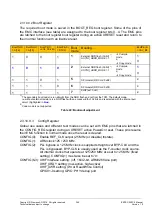
CONFIG
(6)
PIN: A23
CONFIG
(5)
PIN: A22
CONFIG
(4)
PIN: A21
CONFIG
(3)
PIN: A20
CONFIG
(2)
PIN: A19
CONFIG
(1)
PIN: A18
CONFIG
(0)
PIN: A17
Description
-
-
-
-
-
-
1
REF_CLK tristate
-
-
-
-
-
-
0
REF_CLK output (25 MHz)
-
-
-
-
-
0
-
ARM-Clock 125 MHz
-
-
-
-
-
1
-
ARM-Clock 250 MHz
-
-
-
-
0
-
-
CONFIG (2) must be tied to zero
0
0
-
0
-
-
-
XHIF = on, 16 bit Mode,
GPIO94-79 and GPIO61-60 on (all inputs),
XHIF_XWR has Read/Write-Control
0
0
-
1
-
-
-
XHIF = on, 16 bit Mode,
GPIO94-79 and GPIO 61-60 on (all inputs),
XHIF_XRD / XHIF_XWR separated
0
0
0
-
-
-
-
XHIF = on, 16 bit Mode,
GPIO94-79 and GPIO 61-60 on (all inputs),
XHIF_XRDY is high-active
0
0
1
-
-
-
-
XHIF = on, 16 bit Mode,
GPIO94-79 and GPIO61-60 on (all inputs),
XHIF_XRDY is low-active
0
1
-
0
-
-
-
XHIF = on, 32 bit mode, GPIO95-32 off,
XHIF_XWR has Read/Write-Control
0
1
-
1
-
-
-
XHIF = on, 32 bit mode, GPIO95-32 off,
XHIF_XRD / XHIF_XWR separated
0
1
0
-
-
-
-
XHIF = on, 32 bit mode, GPIO95-32 off,
XHIF_XRDY is high-active
0
1
1
-
-
-
-
XHIF = on, 32 bit mode, GPIO95-32 off,
XHIF_XRDY is low-active
1
0
0
1
-
-
-
XHIF = off, GPIO95-32 on (all inputs)
1
1
1
0
-
-
-
XHIF = off, ARM926 Trace Port = on (only at
ARM926 Clock = 125 MHz)
Remainder
-
-
-
reserved
Blue:
Default setting through the internal pulls
Table 23: Configuration adjustment
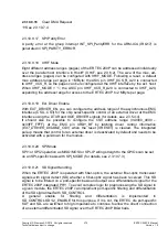
2.3.10.9.4 Reset Registers
Reset control register
: With the control bits in the ASYN_RES_CTRL_REG and
SYN_RES_CTRL_REG registers:
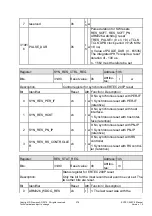
1. An enable for triggering a WD reset for ARM926 and PN-IP can be configured
2. Triggering a
synchronous
module reset for PerIF, HostIF, PN-IP
3. Triggering an
asynchronous
block or module reset in response to the following
events can be activated/deactivated:
Expiry of the watchdog
SW activation of a reset (RES_SOFT, RES_SOFT_...) One-shot bit
Note:
All reset sources are reset with a PowerOn reset (XRESET) only. This prevents a combi-
national loop in the design. The register can only be written word by word. 8-bit and
16-bit accesses produces access errors.
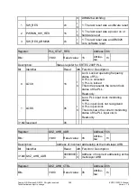
Reset status register:
Active reset events that have occurred since the last PowerOn
reset are saved in RES_STAT_REG. The SW can delete individual bits by writing a '1' to
the bit position. The register is only reset with a PowerOn reset (XRESET).
Содержание ERTEC 200P
Страница 1: ...ERTEC 200P 2 Enhanced Real Time Ethernet Controller Manual ...
Страница 309: ...Copyright Siemens AG 2016 All rights reserved 309 ERTEC 200P 2 Manual Technical data subject to change Version 1 0 ...
Страница 492: ...Copyright Siemens AG 2016 All rights reserved 492 ERTEC 200P 2 Manual Technical data subject to change Version 1 0 ...

